Introduction
As of early 2013, there are now an estimated 6.4 billion worldwide cellular connections. For 2012 alone, IDC market intelligence reports show an estimated 1.1 billion shipments for smart connected devices—smartphones, tablets, laptops, PCs, and so on. However, even more remarkable are the hockey stick growth projections for the years to come: the same IDC reports forecast the new device shipment numbers to climb to over 1.8 billion by 2016, and other cumulative forecasts estimate a total of over 20 billion connected devices by 2020.
With an estimated human population of 7 billion in 2012, rising to 7.5 billion by 2020, these trends illustrate our insatiable appetite for smart connected devices: apparently, most of us are not satisfied with just one.
However, the absolute number of connected devices is only one small part of the overall story. Implicit in this growth is also the insatiable demand for high-speed connectivity, ubiquitous wireless broadband access, and the connected services that must power all of these new devices! This is where, and why, we must turn our conversation to the performance of the various cellular technologies, such as GSM, CDMA, HSPA, and LTE. Chances are, most of your users will be using one of these technologies, some exclusively, to access your site or service. The stakes are high, we have to get this right, and mobile networks definitely pose their own set of performance challenges.
§Brief History of the G’s
Navigating the forest of the various cellular standards, release
versions, and the pros and cons of each could occupy not chapters, but
entire books. Our goal here is much more humble: we need to develop an
intuition for the operating parameters, and their implications, of the
major past and future milestones (Table 7-1) of the dominant wireless
technologies in the market.
Generation
Peak data rate
Description
1G
no data
Analog systems
2G
Kbit/s
First digital systems as overlays or parallel to analog
systems
3G
Mbit/s
Dedicated digital networks deployed in parallel to analog
systems
4G
Gbit/s
Digital and packet-only networks
The first important realization is that the underlying standards for each wireless generation are expressed in terms of peak spectral efficiency (bps/Hz), which is then translated to impressive numbers such as Gbit/s+ peak data rates for 4G networks. However, you should now recognize the key word in the previous sentence: peak! Think back to our earlier discussion on Measuring Real-World Wireless Performance—peak data rates are achieved in ideal conditions.
Regardless of the standard, the real performance of every network will
vary by provider, their configuration of the network, the number of
active users in a given cell, the radio environment in a specific
location, the device in use, plus all the other factors that affect
wireless performance. With that in mind, while there are no guarantees
for data rates in real-world environments, a simple but effective
strategy to calibrate your performance expectations (Table 7-2) is to assume much closer
to the lower bound for data throughput, and toward the higher bound for
packet latency for every generation.
Generation
Data rate
Latency
2G
100–400 Kbit/s
300–1000 ms
3G
0.5–5 Mbit/s
100–500 ms
4G
1–50 Mbit/s
< 100 ms
To complicate matters further, the classification of any given network
as 3G or 4G is definitely too coarse, and correspondingly so is the
expected throughput and latency. To understand why this is the case, and
where the industry is heading, we first need to take a quick survey of
the history of the different technologies and the key players behind
their evolution.
The first commercial 1G network was launched in Japan in 1979. It
was an analog system and offered no data capabilities. In 1991, the
first 2G network was launched in Finland based on the emerging GSM
(Global System for Mobile Communications, originally Groupe Spécial
Mobile) standard, which introduced digital signaling within the radio
network. This enabled first circuit-switched mobile data services, such
as text messaging (SMS), and packet delivery at a whopping peak data
rate of 9.6 Kbit/s!
It wasn’t until the mid 1990s, when general packet radio service
(GPRS) was first introduced to the GSM standard that wireless Internet
access became a practical, albeit still very slow, possibility: with
GPRS, you could now reach 172 Kbit/s, with typical roundtrip latency
hovering in high hundreds of milliseconds. The combination of GPRS and
earlier 2G voice technologies is often described as 2.5G. A few years
later, these networks were enhanced by EDGE (Enhanced Data rates for
GSM Evolution), which increased the peak data rates to 384 Kbit/s. The
first EDGE networks (2.75G) were launched in the U.S. in 2003.
At this point, a pause and some reflection is warranted. Wireless
communication is many decades old, but practical, consumer-oriented
data services over mobile networks are a recent phenomenon! 2.75G
networks are barely a decade old, which is recent history, and are also
still widely used around the world. Yet, most of us now simply can’t
imagine living without high-speed wireless access. The rate of
adoption, and the evolution of the wireless technologies, has been
nothing short of breathtaking.
Once the consumer demand for wireless data services began to grow,
the question of radio network interoperability became a hot issue for
everyone involved. For one, the telecom providers must buy and deploy
the hardware for the radio access network (RAN), which requires
significant capital investments and ongoing maintenance—standard
hardware means lower costs. Similarly, without industry-wide standards,
the users would be restricted to their home networks, limiting the use
cases and convenience of mobile data access.
In response, the European Telecommunication Standards Institute
(ETSI) developed the GSM standard in the early 1990's, which was
quickly adopted by many European countries and around the globe. In
fact, GSM would go on to become the most widely deployed wireless
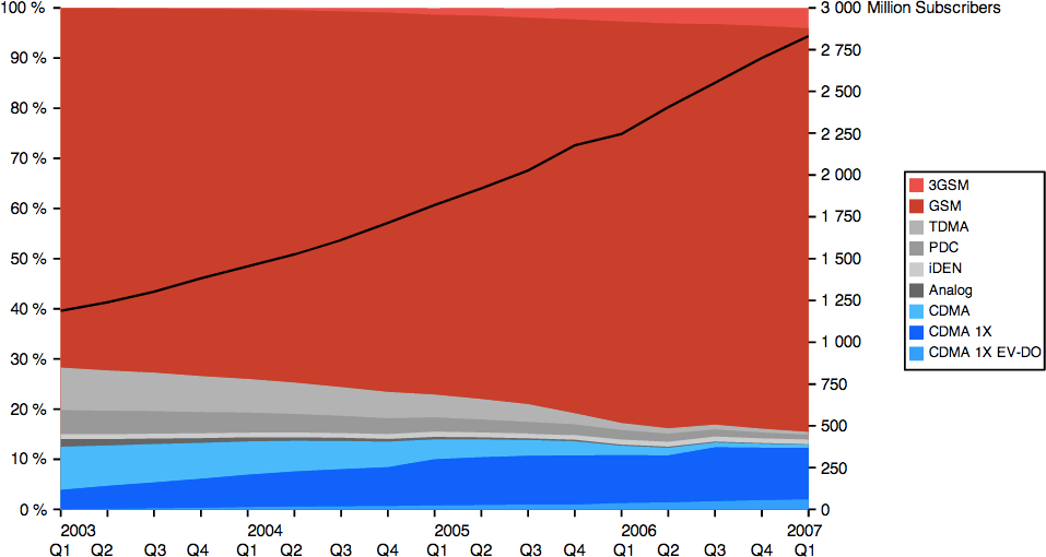
standard, by some estimates, covering 80%–85% of the market
(Figure 7-1).
But it wasn’t the only one. In parallel, the IS-95 standard developed
by Qualcomm also captured 10%–15% of the market, most notably with many
network deployments across North America. As a result, a device
designed for the IS-95 radio network cannot operate on the GSM network,
and vice versa—an unfortunate property that is familiar to many
international travelers.
In 1998, recognizing the need for global evolution of the deployed
standards, as well as defining the requirements for the next generation
(3G) networks, the participants in GSM and IS-95 standards
organizations formed two global partnership projects:
Responsible for developing the Universal Mobile
Telecommunication System (UMTS), which is the 3G upgrade to GSM
networks. Later, it also assumed maintenance of the GSM standard
and development of the new LTE standards.
Responsible for developing the 3G specifications based on the
CDMA2000 technology, which is a successor to the IS-95 standard
developed by Qualcomm.
Consequently, the development of both types of standards
(Table 7-3) and
associated network infrastructure has proceeded in parallel. Perhaps
not directly in lockstep, but nonetheless following mostly similar
evolution of the underlying technologies.
Chances are, you should see some familiar labels on the list: EV-DO,
HSPA, LTE. Many network operators have invested significant marketing
resources, and continue to do so, to promote these technologies as
their "latest and fastest mobile data networks." However, our interest
and the reason for this historical detour is not for the marketing, but
for the macro observations of the evolution of the mobile wireless
industry:
There are two dominant, deployed mobile network types around the
world.
3GPP and 3GPP2 manage the evolution of each technology.
3GPP and 3GPP2 standards are not device interoperable.
There is no one 4G or 3G technology. The International
Telecommunication Union (ITU) sets the international standards and
performance characteristics, such as data rates and latency, for each
wireless generation, and the 3GPP and 3GPP2 organizations then define
the standards to meet and exceed these expectations within the context
of their respective technologies.
How do you know which network type your carrier is using? Simple.
Does your phone have a SIM card? If so, then it is a 3GPP technology
that evolved from GSM. To find out more detailed information about
the network, check your carrier’s FAQ, or if your phone allows it,
check the network information directly on your phone.
For Android users, open your phone dial screen and type in:
In the context of 3G networks, we have two dominant and competing
standards: UMTS and CDMA-based networks, which are developed by 3GPP
and 3GPP2, respectively. However as the earlier table of cellular
standards (Table 7-3) shows, each is also split
into several transitional milestones: 3.5G, 3.75G, and 3.9G
technologies.
Why couldn’t we simply jump to 4G instead? Well, standards take a
long time to develop, but even more importantly, there are big
financial costs for deploying new network infrastructure. As we will
see, 4G requires an entirely different radio interface and parallel
infrastructure to 3G. Because of this, and also for the benefit of the
many users who have purchased 3G handsets, both 3GPP and 3GPP2 have
continued to evolve the existing 3G standards, which also enables the
operators to incrementally upgrade their existing networks to deliver
better performance to their existing users.
Not surprisingly, the throughput, latency, and other performance
characteristics of the various 3G networks have improved, sometimes
dramatically, with every new release. In fact, technically, LTE is
considered a 3.9G transitional standard! However, before we get to LTE,
let’s take a closer look at the various 3GPP and 3GPP2 milestones.
In the case of networks following the 3GPP standards, the
combination of HSDPA and HSUPA releases is often known and marketed
as a High-Speed Packet Access (HSPA) network. This combination of the
two releases enabled low single-digit Mbit/s throughput in real-world
deployments, which was a significant step up from the early 3G
speeds. HSPA networks are often labeled as 3.5G.
From there, the next upgrade was HSPA+ (3.75G), which offered
significantly lower latencies thanks to a simplified core network
architecture and data rates in mid to high single-digit Mbit/s
throughput in real-world deployments. However, as we will see,
release 7, which introduced HSPA+, was not the end of the line for
this technology. In fact, the HSPA+ standards have been continuously
refined since then and are now competing head to head with LTE and
LTE-Advanced!
The CDMA2000 EV-DO standard developed by 3GPP2 followed a similar
network upgrade path. The first release (Rel. 0) enabled low single
digit Mbit/s downlink throughput but very low uplink speeds. The
uplink performance was addressed with Rev. A, and both uplink and
downlink speeds were further improved in Rev. B. Hence, a Rev. B
network was able to deliver mid to high single-digit Mbit/s
performance to its users, which makes it comparable to HSPA and early
HSPA+ networks—aka, 3.5–3.75G.
The Rev. C release is also frequently referred to as EV-DO
Advanced and offers significant operational improvements in capacity
and performance. However, the adoption of EV-DO Advanced has not been
nearly as strong as that of HSPA+. Why? If you paid close attention
to the standards generation table (Table 7-3), you may have noticed that
3GPP2 does not have an official and competing 4G standard!
While 3GPP2 could have continued to evolve its CDMA technologies,
at some point both the network operators and the network vendors
agreed on 3GPP LTE as a common 4G successor to all types of
networks. For this reason, many of the CDMA network operators are
also some of the first to invest into early LTE infrastructure, in
part to be able to compete with ongoing HSPA+ improvements.
In other words, most mobile operators around the world are
converging on HSPA+ and LTE as the future mobile wireless
standards—that’s the good news. Having said that, don’t hold your
breath. Existing 2G and 3–3.75G technologies are still powering the
vast majority of deployed mobile radio networks, and even more
importantly, will remain operational for at least another decade.
3G is often described as "mobile broadband." However, broadband
is a relative term. Some pin it as a communication bandwidth of at
least 256 Kbit/s, others as that exceeding 640 Kbit/s, but the
truth is that the value keeps changing based on the experience we
are trying to achieve. As the services evolve and demand higher
throughput, so does the definition of broadband.
In that light, it might be more useful to think of 3G standards
as those targeting and exceeding the Mbit/s bandwidth threshold.
How far over the Mbit/s barrier? Well, that depends on the release
version of the standard (as we saw earlier), the carrier
configuration of the network, and the capabilities of the device in
use.
Before we dissect the various 4G technologies, it is important to
understand what stands behind the "4G" label. Just as with 3G, there is
no one 4G technology. Rather, 4G is a set of requirements
(IMT-Advanced) that was developed and published by the ITU back in
2008. Any technology that meets these requirements can be labeled as
4G.
Some example requirements of IMT-Advanced include the following:
Based on an IP packet switched network
Interoperable with previous wireless standards (3G and 2G)
100 Mbit/s data rate for mobile clients and Gbit/s+ when
stationary
Sub 100 ms control-plane latency and sub 10 ms user-plane
latency
Dynamic allocation and sharing of network resources between
users
Use of variable bandwidth allocation, from 5 to 20 MHz
The actual list is much, much longer but the preceding captures the
highlights important for our discussion: much higher throughput and
significantly lower latencies when compared to earlier generations.
Armed with these criteria, we now know how to classify a 4G
network—right? Not so fast, that would be too easy! The marketing
departments also had to have their say.
LTE-Advanced is a standard that was specifically developed to
satisfy all the IMT-Advanced criteria. In fact, it was also the first
3GPP standard to do so. However, if you were paying close attention,
you would have noticed that LTE (release 8) and LTE-Advanced (release
10) are, in fact, different standards. Technically, LTE should really
be considered a 3.9G transitional standard, even though it lays much of
the necessary groundwork to meet the 4G requirements—it is almost
there, but not quite!
However, this is where the marketing steps in. The 3G and 4G
trademarks are held by the ITU, and hence their use should correspond
to defined requirements for each generation. Except the carriers won a
marketing coup and were able to redefine the "4G" trademark to include
a set of technologies that are significantly close to the 4G
requirements. For this reason, LTE (release 8) and most HSPA+ networks,
which do not meet the actual technical 4G requirements, are nonetheless
marketed as "4G."
What about the real (LTE-Advanced) 4G deployments? Those are coming,
but it remains to be seen how these networks will be marketed in light
of their earlier predecessors. Regardless, the point is, the "4G" label
as it is used today by many carriers is ambiguous, and you should read
the fine print to understand the technology behind it.
Despite the continuous evolution of the 3G standards, the increased
demand for high data transmission speeds and lower latencies exposed a
number of inherent design limitations in the earlier UMTS technologies.
To address this, 3GPP set out to redesign both the core and the radio
networks, which led to the creation of the aptly named Long Term
Evolution (LTE) standard:
All IP core network
Simplified network architecture to lower costs
Low latencies in user (<10 ms) and control planes (<100
ms)
New radio interface and modulation for high throughput (100
Mbps)
Ability to use larger bandwidth allocations and carrier
aggregation
MIMO as a requirement for all devices
Not surprisingly, the preceding list should read similar to the
IMT-Advanced requirements we saw earlier. LTE (release 8) laid the
groundwork for the new network architecture, and LTE-Advanced (release
10) delivered the necessary improvements to meet the true 4G
requirements set by IMT-Advanced.
At this point it is important to note that due to radio and core
network implementation differences, LTE networks are not simple
upgrades to existing 3G infrastructure. Instead, LTE networks must be
deployed in parallel and on separate spectrum from existing 3G
infrastructure. However, since LTE is a common successor to both UMTS
and CDMA standards, it does provide a way to interoperate with both: an
LTE subscriber can be seamlessly handed off to a 3G network and be
migrated back where LTE infrastructure is available.
Finally, as the name implies, LTE is definitely the long-term
evolution plan for virtually all future mobile networks. The only
question is, how distant is this future? A few carriers have already
begun investing into LTE infrastructure, and many others are beginning
to look for the spectrum, funds, or both, to do so. However, current
industry estimates show that this migration will indeed be a
long-term one—perhaps over the course of the next decade or
so. In the meantime, HSPA+ is set to take the center stage.
Every LTE-capable device must have multiple radios for mandatory
MIMO support. However, each device will also need separate radio
interfaces for earlier 3G and 2G networks. If you are counting, that
translates to three or four radios in every handset! For higher data
rates with LTE, you will need 4x MIMO, which brings the total to five
or six radios. You were wondering why your battery is drained so
quickly?
HSPA+ was first introduced in 3GPP release 7, back in 2007. However,
while the popular attention quickly shifted toward LTE, which was first
introduced in 3GPP release 8 in 2008, what is often overlooked is that
the development of HSPA+ did not cease and continued to coevolve in
parallel. In fact, HSPA+ release 10 meets many of the IMT-Advanced
criteria. But, you may ask, if we have LTE and everyone is in agreement
that it is the standard for future mobile networks, why
continue to develop and invest into HSPA+? As usual, the answer is a
simple one: cost.
3GPP 3G technologies command the lion’s share of the established
wireless market around the world, which translates into huge existing
infrastructure investments by the carriers around the globe. Migrating
to LTE requires development of new radio networks, which once again
translates into significant capital expenditures. By contrast, HSPA+
offers a much more capital efficient route: the carriers can deploy
incremental upgrades to their existing networks and get comparable
performance.
Cost-effectiveness is the name of the game and the reason why
current industry projections (Figure 7-2) show HSPA+ as responsible for the
majority of 4G upgrades around the world for years to come. In the
meantime, CDMA technologies developed by 3GPP2 will continue to
coexist, although their number of subscriptions is projected to start
declining slowly, while new LTE deployments will proceed in parallel
with different rates in different regions—in part due to cost
constraints, and in part due to different regulation and the
availability of required radio spectrum.
For a variety of reasons, North America appears to be the leader in
LTE adoption: current industry projections show the number of LTE
subscribers in U.S. and Canada surpassing that of HSPA by 2016
(Figure 7-3).
However, the rate of LTE adoption in North America appears to be
significantly more aggressive than in most other countries. Within the
global context, HSPA+ is set to be the dominant mobile wireless
technology of the current decade.
While many are first surprised by the trends in the HSPA+ vs. LTE
adoption, this is not an unexpected outcome. If nothing else, it
serves to illustrate an important point: it takes roughly a decade
from the first specification of a new wireless standard to its
mainstream availability in real-world wireless networks.
By extension, it is a fairly safe bet that we will be talking
about LTE-Advanced in earnest by the early 2020s! Unfortunately,
deploying new radio infrastructure is a costly and time-consuming
proposition.
Crystal ball gazing is a dangerous practice in our industry.
However, by this point we have covered enough to make some reasonable
predictions about what we can and should expect out of the currently
deployed mobile networks, as well as where we might be in a few years’
time.
First, the wireless standards are evolving quickly, but the physical
rollout of these networks is both a costly and a time-consuming
exercise. Further, once deployed, the network must be maintained for
significant amounts of time to recoup the costs and to keep existing
customers online. In other words, while there is a lot of hype and
marketing around 4G, older-generation networks will continue to operate
for at least another decade. When building for the mobile web, plan
accordingly.
Ironically, while 4G networks provide significant improvements for
IP data delivery, 3G networks are still much more efficient in
handling the old-fashioned voice traffic! Voice over LTE (VoLTE) is
currently in active development and aims to enable efficient and
reliable voice over 4G, but most current 4G deployments still rely on
the older, circuit-switched infrastructure for voice delivery.
Consequently, when building applications for mobile networks, we
cannot target a single type or generation of network, or worse, hope
for specific throughput or latency performance. As we saw, the actual
performance of any network is highly variable, based on deployed
release, infrastructure, radio conditions, and a dozen other variables.
Our applications should adapt to the continuously changing conditions
within the network: throughput, latency, and even the availability of
the radio connection. When the user is on the go, it is highly likely
that he may transition between multiple generations of networks (LTE,
HSPA+, HSPA, EV-DO, and even GPRS Edge) based on the available coverage
and signal strength. If the application fails to account for this, then
the user experience will suffer.
The good news is HSPA+ and LTE adoption is growing very fast, which
enables an entirely new class of high-throughput and latency-sensitive
applications previously not possible. Both are effectively on par in
throughput and latency (Table 7-6): mid to high digit Mbps
throughput in real-world environments, and sub-100-millisecond latency,
which makes them comparable to many home and office WiFi networks.
However, while 4G wireless performance is often compared to that of
WiFi, or wired broadband, it would be incorrect to assume that we can
get away with treating them as the same environments: that they are
definitely not.
For example, most users and developers expect an "always on"
experience where the device is permanently connected to the Internet
and is ready to instantaneously react to user input or an incoming data
packet. This assumption holds true in the tethered world but is
definitely incorrect for mobile networks. Practical constraints such as
battery life and device capabilities mean that we must design our
applications with explicit awareness of the constraints of mobile
networks. To understand these differences, let’s dig a little deeper.
§First Data Services
with 2G
§3GPP and 3GPP2
Partnerships
Generation
Organization
Release
2G
3GPP
GSM
3GPP2
IS-95 (cdmaOne)
2.5G, 2.75G
3GPP
GPRS, EDGE (EGPRS)
3GPP2
CDMA2000
3G
3GPP
UMTS
3GPP2
CDMA 2000 1x EV-DO Release 0
3.5G, 3.75G, 3.9G
3GPP
HSPA, HSPA+, LTE
3GPP2
EV-DO Revision A, EV-DO Revision B, EV-DO Advanced
4G
3GPP
LTE-Advanced, HSPA+ Revision 11+
*#*#4636#*#*. If your phone allows it, it should open a
diagnostics screen where you can inspect the status and type of your
mobile connection, battery diagnostics, and more.
§Evolution of 3G
Technologies
Evolution of 3GPP technologies
Release
Date
Summary
99
1999
First release of the UMTS standard
4
2001
Introduced an all-IP core network
5
2002
Introduced High-Speed Packet Downlink Access (HSDPA)
6
2004
Introduced High-Speed Packet Uplink Access (HSUPA)
7
2007
Introduced High-Speed Packet Access Evolution (HSPA+)
8
2008
Introduced new LTE System Architecture Evolution (SAE)
9
2009
Improvements to SAE and WiMAX interoperability
10
2010
Introduced 4G LTE-Advanced architecture
Evolution of 3GPP2 technologies
Release
Date
Summary
Rel. 0
1999
First release of the 1x EV-DO standard
Rev. A
2001
Upgrade to peak data-rate, lower latency, and QoS
Rev. B
2004
Introduced multicarrier capabilities to Rev. A
Rev. C
2007
Improved core network efficiency and performance
§IMT-Advanced 4G
Requirements
§Long Term Evolution (LTE)
§HSPA+ is
Leading Worldwide 4G Adoption


§Building
for the Multigeneration Future
HSPA+
LTE
LTE-Advanced
Peak downlink speed (Mbit/s)
168
300
3,000
Peak uplink speed (Mbit/s)
22
75
1,500
Maximum MIMO streams
2
4
8
Idle to connected latency (ms)
< 100
< 100
< 50
Dormant to active latency (ms)
< 50
< 50
< 10
User-plane one-way latency (ms)
< 10
< 5
< 5
§Device Features and Capabilities
What is often forgotten is that the deployed radio network is only half of the equation. It goes without saying that devices from different manufacturers and release dates will have very different characteristics: CPU speeds and core counts, amount of available memory, storage capacity, GPU, and more. Each of these factors will affect the overall performance of the device and the applications running on it.
However, even with all of these variables accounted for, when it comes
to network performance, there is one more section that is often
overlooked: radio capabilities. Specifically, the device that the user is
holding in her hands must also be able to take advantage of the deployed
radio infrastructure! The carrier may deploy the latest LTE
infrastructure, but a device designed for an earlier release may simply
not be able to take advantage of it, and vice versa.
Both the 3GPP and 3GPP2 standards continue to evolve and enhance the
radio interface requirements: modulation schemes, number of radios, and
so on. To get the best performance out of any network, the device must
also meet the specified user equipment (UE) category requirements for
each type of network. In fact, for each release, there are often
multiple UE categories, each of which will offer very different radio
performance.
An obvious and important question is, why? Once again, the answer is
a simple one: cost. Availability of multiple categories of devices
enables device differentiation, various price points for
price-sensitive users, and ability to adapt to deployed network
infrastructure on the ground.
The HSPA standard alone specifies over 36 possible UE categories!
Hence, just saying that you have an "HSPA capable device"
(Table 7-7) is not
enough—you need to read the fine print. For example, assuming the radio
network is capable, to get the 42.2 Mbps/s throughput, you would also
need a category 20 (2x MIMO), or category 24 (dual-cell) device.
Finally, to confuse matters further, a category 21 device does not
automatically guarantee higher throughput over a category 20 handset.
Similarly, the LTE standard defines its own set of user equipment
categories (Table 7-8): a
high-end smartphone is likely to be a category 3–5 device, but it will
also likely share the network with a lot of cheaper category 1–2
neighbors. Higher UE categories, which require 4x and even 8x MIMO, are
more likely to be found in specialized devices—powering that many
radios simultaneously consumes a lot of power, which may not be very
practical for something in your pocket!
In practice, most of the early LTE deployments are targeting
category 1–3 devices, with early LTE-Advanced networks focusing on
category 3 as their primary UE type.
If you own an LTE or an HSPA+ device, do you know its category
classification? And once you figure that out, do you know which 3GPP
release your network operator is running? To get the best performance,
the two must match. Otherwise, you will be limited either by the
capabilities of the radio network or the device in use.
§User Equipment Category
3GPP Release
Category
MIMO, Multicell
Peak data rate (Mbit/s)
5
8
—
7.2
5
10
—
14.0
7
14
—
21.1
8
20
2x MIMO
42.2
8
21
Dual-cell
23.4
8
24
Dual-cell
42.2
10
32
Quad-cell + MIMO
168.8
3GPP release
Category
MIMO
Peak downlink (Mbit/s)
Peak uplink (Mbit/s)
8
1
1x
10.3
5.2
8
2
2x
51.0
25.5
8
3
2x
102.0
51.0
8
4
2x
150.8
51.0
8
5
4x
299.6
75.4
10
6
2x or 4x
301.5
51.0
10
7
2x or 4x
301.5
102.0
10
8
8x
2998.6
1497.8
§Radio Resource Controller (RRC)
Both 3G and 4G networks have a unique feature that is not present in
tethered and even WiFi networks. The Radio Resource Controller (RRC)
mediates all connection management between the device in use and the
radio base station (Figure 7-4). Understanding why it exists, and how
it affects the performance of every device on a mobile network, is
critical to building high-performance mobile applications. The RRC has
direct impact on latency, throughput, and battery life of the device in
use.

When using a physical connection, such as an Ethernet cable, your computer has a direct and an always-on network link, which allows either side of this connection to send data packets at any time; this is the best possible case for minimizing latency. As we saw in From Ethernet to a Wireless LAN, the WiFi standard follows a similar model, where each device is able to transmit at any point in time. This too provides minimum latency in the best case, but due to the use of the shared radio medium can also lead to high collision rates and unpredictable performance if there are many active users. Further, because any WiFi peer could start transmitting at any time, all others must also be ready to receive. The radio is always on, which consumes a lot of power.
In practice, keeping the WiFi radio active at all times is simply too expensive, as battery capacity is a limited resource on most devices. Hence, WiFi offers a small power optimization where the access point broadcasts a delivery traffic indication message (DTIM) within a periodic beacon frame to indicate that it will be transmitting data for certain clients immediately after. In turn, the clients can listen for these DTIM frames as hints for when the radio should be ready to receive, and otherwise the radio can sleep until the next DTIM transmission. This lowers battery use but adds extra latency.
The upcoming WiFi Multimedia (WMM) standard will further improve the power efficiency of WiFi devices with the help of the new PowerSave mechanisms such as NoAck and APSD (Automatic Power Save Delivery).
Therein lies the problem for 3G and 4G networks: network efficiency and power. Or rather, lack of power, due to the fact that mobile devices are constrained by their battery capacity and a requirement for high network efficiency among a significantly larger number of active users in the cell. This is why the RRC exists.
As the name implies, the Radio Resource Controller assumes full responsibility over scheduling of who talks when, allocated bandwidth, the signal power used, the power state of each device, and a dozen other variables. Simply put, the RRC is the brains of the radio access network. Want to send data over the wireless channel? You must first ask the RRC to allocate some radio resources for you. Have incoming data from the Internet? The RRC will notify you for when to listen to receive the inbound packets.
The good news is all the RRC management is performed by the network. The bad news is, while you can’t necessarily control the RRC via an API, if you do want to optimize your application for 3G and 4G networks, then you need to be aware of and work within the constraints imposed by the RRC.
The RRC lives within the radio network. In 2G and 3G networks, the RRC lived in the core carrier network, and in 4G the RRC logic has been moved directly to the serving radio tower (eNodeB) to improve performance and reduce coordination latency.
§3G, 4G, and WiFi Power Requirements
The radio is one of the most power-hungry components of any handset. In fact, the screen is the only component that consumes higher amounts of power when active—emphasis on active. In practice, the screen is off for significant periods of time, whereas the radio must maintain the illusion of an "always-on" experience such that the user is reachable at any point in time.
One way to achieve this goal is to keep the radio active at all times, but even with the latest advances in battery capacity, doing so would drain the battery in a matter of hours. Worse, latest iterations of the 3G and 4G standards require parallel transmissions (MIMO, Multicell, etc.), which is equivalent to powering multiple radios at once. In practice, a balance must be struck between keeping the radio active to service low-latency interactive traffic and cycling into low-power states to enable reasonable battery performance.
How do the different technologies compare, and which is better for battery life? There is no one single answer. With WiFi, each device sets its own transmit power, which is usually in the 30–200 mW range. By comparison, the transmit power of the 3G/4G radio is managed by the network and can consume as low as 15 mW when in an idle state. However, to account for larger range and interference, the same radio can require 1,000–3,500 mW when transmitting in a high-power state!
In practice, when transferring large amounts of data, WiFi is often far more efficient if the signal strength is good. But if the device is mostly idle, then the 3G/4G radio is more effective. For best performance, ideally we would want dynamic switching between the different connection types. However, at least for the moment, no such mechanism exists. This is an active area of research, both in the industry and academia.
So how does the battery and power management affect networking performance? Signal power (explained Signal Power) is one of the primary levers to achieve higher throughput. However, high transmit power consumes significant amounts of energy and hence may be throttled to achieve better battery life. Similarly, powering down the radio may also tear down the radio link to the radio tower altogether, which means that in the event of a new transmission, a series of control messages must be first exchanged to reestablish the radio context, which can add tens and even hundreds of milliseconds of latency.
Both throughput and latency performance are directly impacted by the power management profile of the device in use. In fact, and this is key, in 3G and 4G networks the radio power management is controlled by the RRC: not only does it tell you when to communicate, but it will also tell you the transmit power and when to cycle into different power states.
§LTE RRC State Machine
The radio state of every LTE device is controlled by the radio tower
currently servicing the user. In fact, the 3GPP standard defines a
well-specified state machine, which describes the possible power states
of each device connected to the network (Figure 7-5). The network operator can make
modifications to the parameters that trigger the state transitions, but
the state machine itself is the same across all LTE deployments.

- RRC Idle
-
Device radio is in a low-power state (<15 mW) and only listening to control traffic. No radio resources are assigned to the client within the carrier network.
- RRC Connected
-
Device radio is in a high-power state (1000–3500 mW) while it either transmits data or waits for data, and dedicated radio resources are allocated by the radio network.
The device is either idle, in which case it is only listening to control channel broadcasts, such as paging notifications of inbound traffic, or connected, in which case the network has an established context and resource assignment for the client.
When in an idle state, the device cannot send or receive any data. To do so, it must first synchronize itself to the network by listening to the network broadcasts and then issue a request to the RRC to be moved to the "connected" state. This negotiation can take several roundtrips to establish, and the 3GPP LTE specification allocates a target of 100 milliseconds or less for this state transition. In LTE-Advanced, the target time was further reduced to 50 milliseconds.
Once in a connected state, a network context is established between the radio tower and the LTE device, and data can be transferred. However, once either side completes the intended data transfer, how does the RRC know when to transition the device to a lower power state? Trick question—it doesn’t!
IP traffic is bursty, optimized TCP connections are long-lived, and UDP traffic provides no "end of transmission" indicator by design. As a result, and not unlike the NAT connection-state timeouts solution covered Connection-State Timeouts, the RRC state machine depends on a collection of timers to trigger the RRC state transitions.
Finally, because the connected state requires such high amounts of power, multiple sub-states are available (Figure 7-5) to allow for more efficient operation:
- Continuous reception
-
Highest power state, established network context, allocated network resources.
- Short Discontinuous Reception (Short DRX)
-
Established network context, no allocated network resources.
- Long Discontinuous Reception (Long DRX)
-
Established network context, no allocated network resources.
In the high-power state, the RRC creates a reservation for the device to receive and transmit data over the wireless interface and notifies the device for what these time-slots are, the transmit power that must be used, the modulation scheme, and a dozen other variables. Then, if the device has been idle for a configured period of time, it is transitioned to a Short DRX power state, where the network context is still maintained, but no specific radio resources are assigned. When in Short DRX state, the device only listens to periodic broadcasts from the network, which allows it to preserve the battery—not unlike the DTIM interval in WiFi.
If the radio remains idle long enough, it is then transitioned to
the Long DRX state, which is identical to the Short DRX state, except
that the device sleeps for longer periods of time between waking up to
listen to the broadcasts (Figure 7-6).

What happens if the network or the mobile device must transmit data when the radio is in one of Short or Long DRX (dormant) states? The device and the RRC must first exchange control messages to negotiate when to transmit and when to listen to radio broadcasts. For LTE, this negotiation time ("dormant to connected") is specified as less than 50 milliseconds, and further tightened to less than 10 milliseconds for LTE-Advanced.
So what does this all mean in practice? Depending on which power
state the radio is in, an LTE device may first require anywhere from 10
to 100 milliseconds (Table 7-9) of latency to negotiate the
required resources with the RRC. Following that, application data can
be transferred over the wireless link, through the carrier’s network,
and then out to the public Internet. Planning for these delays,
especially when designing latency-sensitive applications, can be all
the difference between "unpredictable performance" and an optimized
mobile application.
LTE
LTE-Advanced
Idle to connected latency
< 100 ms
< 50 ms
DRX to connected latency
< 50 ms
< 10 ms
User-plane one-way latency
< 5 ms
< 5 ms
§HSPA and HSPA+ (UMTS) RRC State Machine
Earlier generation 3GPP networks prior to LTE and LTE-Advanced have
a very similar RRC state machine that is also maintained by the radio
network. That’s the good news. The bad news is the state machine for
earlier generations is a bit more complicated (Figure 7-7), and the latencies are much, much
higher. In fact, one reason why LTE offers better performance is
precisely due to the simplified architecture and improved performance
of the RRC state transitions.

- Idle
-
Similar to idle in LTE. The device radio is in a low-power state and only listening to control traffic from the network. No radio resources are assigned to the client within the carrier network.
- Cell DCH
-
Similar to connected LTE mode when in continuous reception. The device is in a high-power state, and network resources are assigned both for upstream and downstream data transfer.
- Cell FACH
-
An intermediate power state, which consumes significantly less power than DCH. The device does not have dedicated network resources but is nonetheless able to transmit small amounts of user data through a shared low-speed channel (with speeds of typically less than 20 Kbps).
Idle and DCH states are nearly identical to that of idle and connected in LTE. However, the intermediate FACH state is unique to UMTS networks (HSPA, HSPA+) and allows the use of a common channel for small data transfers: slow, steady, and consuming roughly half the power of the DCH state. In practice, this state was designed to handle non-interactive traffic, such as periodic polling and status checks done by many background applications.
Not surprisingly, the transition from DCH to FACH is triggered by a timer. However, once in FACH, what triggers a promotion back to DCH? Each device maintains a buffer of data to be sent, and as long as the buffer does not exceed a network-configured threshold, typically anywhere from 100 to 1,000 bytes, then the device can remain in the intermediate state. Finally, if no data is transferred while in FACH for some period of time, another timer transitions the device down to the idle state.
Unlike LTE, which offers two intermediate states (Short DRX and Long DRX), UMTS devices have just a single intermediate state: FACH. However, even though LTE offers a theoretically higher degree of power control, the radios themselves tend to consume more power in LTE devices; higher throughput comes at a cost of increased battery consumption. Hence, LTE devices still have a much higher power profile than their 3G predecessors.
Individual power states aside, perhaps the biggest difference between the earlier-generation 3G networks and LTE is the latency of the state transitions. Where LTE targets sub-hundred milliseconds for idle to connected states, the same transition from idle to DCH can take up to two seconds and require tens of control messages between the 3G device and the RRC! FACH to DCH is not much better either, requiring up to one and a half seconds for the state transition.
The good news is the latest HSPA+ networks have made significant improvements in this department and are now competitive with LTE (Table 7-6). However, we can’t count on ubiquitous access to 4G or HSPA+ networks; older generation 3G networks will continue to exist for at least another decade. Hence, all mobile applications should plan for multisecond RRC latency delays when accessing the network over a 3G interface.
§EV-DO (CDMA) RRC State Machine
While 3GPP standards such as HSPA, HSPA+, and LTE are the dominant network standards around the globe, it is important that we don’t forget the 3GPP2 CDMA based networks. The growth curve for EV-DO networks may look comparatively flat, but even so, current industry projections show nearly half a billion CDMA powered wireless subscriptions by 2017.
Not surprisingly, regardless of the differences in the standards,
the fundamental limitations are the same in UMTS- and CDMA-based
networks: battery power is a constraining resource, radios are
expensive to operate, and network efficiency is an important goal.
Consequently, CDMA networks also have an RRC state machine
(Figure 7-8), which
controls the radio state of each device.

- Idle
-
Similar to idle in 3GPP standards. The device radio is in a low-power state and only listening to control traffic from the network. No radio resources are assigned to the client within the carrier network.
- Connected
-
Similar to connected LTE mode and DCH in HSPA. The device is in a high-power state and network resources are assigned for both upstream and downstream data transfers.
This is definitely the simplest RRC state machine out of all the ones we have examined: the device is either in a high-power state, with allocated network resources, or it is idle. Further, all network transfers require a transition to a connected state, the latency for which is similar to that of HSPA networks: hundreds to thousands of milliseconds depending on the revision of the deployed infrastructure. There are no other intermediate states, and transitions back to idle are also controlled via carrier configured timeouts.
§Inefficiency of Periodic Transfers
An important consequence of the timeout-driven radio state transitions, regardless of the generation or the underlying standard, is that it is very easy to construct network access patterns that can yield both poor user experience for interactive traffic and poor battery performance. In fact, all you have to do is wait long enough for the radio to transition to a lower-power state, and then trigger a network access to force an RRC transition!
To illustrate the problem, let’s assume that the device is on an HSPA+ network, which is configured to move from DCH to FACH state after 10 seconds of radio inactivity. Next, we load an application that schedules an intermittent transfer, such as a real-time analytics beacon, on an 11-second interval. What’s the net result? The device may end up spending hundreds of milliseconds in data transfer and otherwise idle while in a high-power state. Worse, it would transition into the low-power state only to be woken up again a few hundred milliseconds later—worst-case scenario for latency and battery performance.
Every radio transmission, no matter how small, forces a transition
to a high-power state. Then, once the transmission is done, the radio
will remain in this high-power state until the inactivity timer has
expired (Figure 7-9).
The size of the actual data transfer does not influence the timer.
Further, the device may then also have to cycle through several more
intermediate states before it can return back to idle.

The "energy tails" generated by the timer-driven state transitions make periodic transfers a very inefficient network access pattern on mobile networks. First, you have to pay the latency cost of the state transition, then the transfer happens, and finally the radio idles, wasting power, until all the timers fire and the device can return to the low-power state.
§End-to-End Carrier Architecture
Now that we have familiarized ourselves with the RRC and device capabilities, it is useful to zoom out and consider the overall end-to-end architecture of a carrier network. Our goal here is not to become experts in the nomenclature and function of every component, of which there are dozens, but rather to highlight the components that have a direct impact on how the data flows through the carrier network and reasons why it may affect the performance of our applications.
The specific infrastructure and names of various logical and physical components within a carrier network depend on the generation and type of deployed network: EV-DO vs. HSPA vs. LTE, and so on. However, there are also many similarities among all of them, and in this chapter we’ll examine the high-level architecture of an LTE network.
Why LTE? First, it is the most likely architecture for new carrier
deployments. Second, and even more importantly, one of the key features
of LTE is its simplified architecture: fewer components and fewer
dependencies also enable improved performance.
The radio access network (RAN) is the first big logical component of
every carrier network (Figure 7-10), whose primary responsibility
is to mediate access to the provisioned radio channel and shuttle the
data packets to and from the user’s device. In fact, this is the
component controlled and mediated by the Radio Resource Controller. In
LTE, each radio base station (eNodeB) hosts the RRC, which maintains
the RRC state machine and performs all resource assignment for each
active user in its cell.
Whenever a user has a stronger signal from a nearby cell, or if his
current cell is overloaded, he may be handed off to a neighboring
tower. However, while this sounds simple on paper, the hand-off
procedure is also the reason for much of the additional complexity
within every carrier network. If all users always remained in the same
fixed position, and stayed within reach of a single tower, then a
static routing topology would suffice. However, as we all know, that is
simply not the case: users are mobile and must be migrated from tower
to tower, and the migration process should not interrupt any voice or
data traffic. Needless to say, this is a nontrivial problem.
First of all, if the user’s device can be associated with any radio
tower, how do we know where to route the incoming packets? Of course,
there is no magic: the radio access network must communicate with the
core network to keep track of the location of every user. Further, to
handle the transparent handoff, it must also be able to dynamically
update its existing tunnels and routes without interrupting any
existing, user-initiated voice and data sessions.
In LTE, a tower-to-tower handoff can be performed within hundreds
of milliseconds, which will yield a slight pause in data delivery at
the physical layer, but otherwise this procedure is completely
transparent to the user and to all applications running on her
device. In earlier-generation networks, this same process can take up
to several seconds.
However, we’re not done yet. Radio handoffs can be a frequent
occurrence, especially in high-density urban and office environments,
and requiring the user’s device to continuously perform the cell
handoff negotiations, even when the device is idle, would consume a lot
of energy on the device. Hence, an additional layer of indirection was
added: one or more radio towers are said to form a "tracking area,"
which is a logical grouping of towers defined by the carrier network.
The core network must know the location of the user, but frequently
it knows only the tracking area and not the specific tower currently
servicing the user—as we will see, this has important implications on
the latency of inbound data packets. In turn, the device is allowed to
migrate between towers within the same tracking area with no overhead:
if the device is in idle RRC state, no notifications are emitted by the
device or the radio network, which saves energy on the mobile handset.
The core network (Figure 7-11), which is also known as the
Evolved Packet Core (EPC) in LTE is responsible for the data routing,
accounting, and policy management. Put simply, it is the piece that
connects the radio network to the public Internet.
First, we have the packet gateway (PGW), which is the public gateway
that connects the mobile carrier to the public Internet. The PGW is the
termination point for all external connections, regardless of the
protocol. When a mobile device is connected to the carrier network, the
IP address of the device is allocated and maintained by the PGW.
Each device within the carrier network has an internal identifier,
which is independent of the assigned IP address. In turn, once a packet
is received by the PGW, it is encapsulated and tunneled through the EPC
to the radio access network. LTE uses Stream Control Transmission
Protocol (SCTP) for control-plane traffic and a combination of GPRS
Tunneling Protocol (GTP) and UDP for all other data.
The PGW also performs all the common policy enforcement, such as
packet filtering and inspection, QoS assignment, DoS protection, and
more. The Policy and Charging Rules Function (PCRF) component is
responsible for maintaining and evaluating these rules for the packet
gateway. PCRF is a logical component, meaning it can be part of the
PGW, or it can stand on its own.
Now, let’s say the PGW has received a packet from the public
Internet for one of the mobile devices on its network; where does it
route the data? The PGW has no knowledge of the actual location of the
user, nor the different tracking areas within the radio access network.
This next step is the responsibility of the Serving Gateway (SGW) and
the Mobility Management Entity (MME).
The PGW routes all of its packets to the SGW. However, to make
matters even more complicated, the SGW may not know the exact location
of the user either. This function is, in fact, one of the core
responsibilities of the MME. The Mobility Management Entity component
is effectively a user database, which manages all the state for every
user on the network: their location on the network, type of account,
billing status, enabled services, plus all other user metadata.
Whenever a user’s location within the network changes, the location
update is sent to the MME; when the user turns on their phone, the
authentication is performed by the MME, and so on.
Hence, when a packet arrives at the SGW, a query to the MME is sent
for the location of the user. Then, once the MME returns the answer,
which contains the tracking area and the ID of the specific tower
serving the target device, the SGW can establish a connection to the
tower if none exists and route the user data to the radio access
network.
In a nutshell, that is all there is to it. This high-level
architecture is effectively the same in all the different generations
of mobile data networks. The names of the logical components may
differ, but fundamentally all mobile networks are subject to the
following workflow:
Data arrives at the external packet gateway, which connects the
core network to the public Internet.
A set of routing and packet policies is applied at the packet
gateway.
Data is routed from the public gateway to one or more serving
gateways, which act as mobility anchors for the devices within the
radio network.
A user database service performs the authentication, billing,
provisioning of services, and location tracking of each user on the
network.
Once the location of the user within the radio network is
determined, the data is routed from the serving gateway to the
appropriate radio tower.
The radio tower performs the necessary resource assignment and
negotiation with the target device and then delivers the data over
the radio interface.
An important factor in the performance of any carrier network is the
provisioned connectivity and capacity between all the logical and
physical components. The LTE radio interface may be capable of reaching
up to 100 Mbps between the user and the radio tower, but once the
signal is received by the radio tower, sufficient capacity must be
available to transport all this data through the carrier network and
toward its actual destination. Plus, let’s not forget that a single
tower should be able to service many active users simultaneously!
Delivering a true 4G experience is not a simple matter of deploying
the new radio network. The core network must also be upgraded,
sufficient capacity links must be present between the EPC and the radio
network, and all the EPC components must be able to process much higher
data rates with much lower latencies than in any previous generation
network.
In practice, a single radio tower may serve up to three nearby
radio cells, which can easily add up to hundreds of active users.
With 10+ Mbps data rate requirements per user, each tower needs a
dedicated fiber link!
Needless to say, all of these requirements make 4G networks a costly
proposition to the carrier: running fiber to all the radio stations,
high-performance routers, and so on. In practice, it is now not unusual
to find the overall performance of the network being limited not by the
radio interface, but by the available backhaul capacity of the carrier
network.
These performance bottlenecks are not something we can control as
developers of mobile applications, but they do, once again, illustrate
an important fact: the architecture of our IP networks is based on a
best effort delivery model, which makes no guarantees about end-to-end
performance. Once we remove the bottleneck from the first hop, which is
the wireless interface, we move the bottleneck to the next slowest link
in the network, either within the carrier network or somewhere else on
the path toward our destination. In fact, this is nothing new; recall
our earlier discussion on Last-Mile
Latency in wired networks.
Just because you are connected over a 4G interface doesn’t mean you
are guaranteed the maximum throughput offered by the radio interface.
Instead, our applications must adapt to the continuously changing
network weather over the wireless channel, within the carrier network,
and on the public Internet.
§Radio Access Network (RAN)

§Core Network (CN)

§Backhaul Capacity
and Latency
§Packet Flow in a Mobile Network
One of the primary complaints about designing applications for the
mobile web is the high variability in latency. Well, now that we have
covered the RRC and the high-level architecture of a mobile network, we
can finally connect the dots and see the end-to-end flow of the data
packets, which should also explain why this variability exists. Even
better, as we will see, much of the variability is actually very much
predictable!
To start, let’s assume that the user has already authenticated with
a 4G network and the mobile device is idle. Next, the user types in a
URL and hits "Go." What happens next?
First, because the phone is in idle RRC state, the radio must
synchronize with the nearby radio tower and send a request for a new
radio context to be established (Figure 7-12, step 1)—this negotiation requires
several roundtrips between the handset and the radio tower, which may
take up to 100 milliseconds. For earlier-generation networks, where the
RRC is managed by the serving gateway, this negotiation latency is much
higher—up to several seconds.
Once the radio context is established, the device has a resource
assignment from the radio tower and is able to transmit data (step 2)
at a specified rate and signal power. The time to transmit a packet of
data from the user’s radio to the tower is known as the "user-plane
one-way latency" and takes up to five milliseconds for 4G networks.
Hence, the first packet incurs a much higher delay due to the need to
perform the RRC transition, but packets immediately after incur only
the constant first-hop latency cost, as long as the radio stays in the
high-power state.
However, we are not done yet, as we have only transferred our
packets from the device to the radio tower! From here, the packets have
to travel through the core network—through the SGW to the PGW (step
3)—and out to the public Internet (step 4). Unfortunately, the 4G
standards make no guarantees on latency of this path, and hence this
latency will vary from carrier to carrier.
In practice, the end-to-end latency of many deployed 4G networks
tends to be in the 30–100 ms range once the device is in a connected
state—that is to say, without the control plane latency incurred by
the initial packet. Hence, if up to 5 ms of the total time is
accounted for on the first wireless hop, then the rest (25–95 ms) is
the routing and transit overhead within the core network of the
carrier.
Next, let’s say the browser has fetched the requested page and the
user is engaging with the content. The radio has been idle for a few
dozen seconds, which means that the RRC has likely moved the user into
a DRX state (LTE RRC
State Machine) to conserve battery power and to free up network
resources for other users. At this point, the user decides to navigate
to a different destination in the browser and hence triggers a new
request. What happens now?
Nearly the same workflow is repeated as we just saw, except that
because the device was in a dormant (DRX) state, a slightly quicker
negotiation (Figure 7-12, step 1) can take place between the
device and the radio tower—up to 50 milliseconds (Table 7-9) for dormant to connected.
In summary, a user initiating a new request incurs several different
latencies:
Fixed, one-time latency cost incurred for RRC negotiation and
state transitions: <100 ms for idle to active, and <50 ms for
dormant to active.
Fixed cost for every application packet transferred between the
device and the radio tower: <5 ms.
Carrier dependent cost for transporting the packet from the
radio tower to the packet gateway: in practice, 30–100 ms.
Variable latency cost between the carrier’s packet gateway and
the destination address on the public Internet.
The first two latencies are bounded by the 4G requirements, the core
network latency is carrier specific, and the final piece is something
you can influence by strategically positioning your servers closer to
the user; see the earlier discussion on
Speed of Light and Propagation Latency.
Now let’s examine the opposite scenario: the user’s device is idle,
but a data packet must be routed from the PGW to the user
(Figure 7-13).
Once again, recall that all connections are terminated at the PGW,
which means that the device can be idle, with its radio off, but the
connection the device may have established earlier, such as a
long-lived TCP session, can still be active at the PGW.
As we saw earlier, the PGW routes the inbound packet to the SGW
(step 1), which in turn queries the MME. However, the MME may not know
the exact tower currently servicing the user; recall that a collection
of radio towers form a "tracking area." Whenever a user enters a
different tracking area, its location is updated in the MME, but tower
handoffs within the same tracking area do not trigger an update to the
MME.
Instead, if the device is idle, the MME sends a paging message (step
2) to all the towers in the tracking area, which in turn all broadcast
a notification (step 3) on a shared radio channel, indicating that the
device should reestablish its radio context to receive the inbound
data. The device periodically wakes to listen to the paging messages,
and if it finds itself on the paging list, then it initiates the
negotiation (step 4) with the radio tower to reestablish the radio
context.
Once the radio context is established, the tower that performed the
negotiation sends a message back (step 5) to the MME indicating where
the user is, the MME returns the answer to the serving gateway, and the
gateway finally routes the message (step 6) to the tower, which then
delivers (step 7) the message to the device! Phew.
Once the device is in a connected state, a direct tunnel is
established between the radio tower and the serving gateway, which
means that further incoming packets are routed directly to the tower
without the paging overhead, skipping steps 2–5. Once again, the first
packet incurs a much higher latency cost on mobile networks! Plan for
it.
The preceding packet workflow is transparent to IP and all layers
above it, including our applications: the packets are buffered by the
PGW, SGW, and the eNodeB at each stage until they can be routed to
the device. In practice, this translates to observable latency jitter
in packet arrival times, with the first packet incurring the highest
delays due to control-plane negotiation.
§Initiating a Request

§Inbound Data Flow

§Heterogeneous Networks (HetNets)
Existing 4G radio and modulation technologies are already within reach of the theoretical limits of the wireless channel. Hence, the next order of magnitude in wireless performance will not come from improvements in the radio interfaces, but rather from smarter topologies of the wireless networks—specifically, through wide deployment of multilayer heterogeneous networks (HetNets), which will also require many improvements in the intra-cell coordination, handoff, and interference management.
The core idea behind HetNets is a simple one: instead of relying on
just the macro coverage of a large geographic area, which creates a lot
of competition for all users, we can also cover the area with many small
cells (Figure 7-14), each of
which can minimize path loss, require lower transmit power, and enable
better performance for all users.

A single macrocell can cover up to tens of square miles in low-density wireless environments, but in practice, in high-density urban and office settings, can be limited to anywhere from just 50 to 300 meters! In other words, it can cover a small block, or a few buildings. By comparison, microcells are designed to cover a specific building; picocells can service one or more separate floors, and femtocells can cover a small apartment and leverage your existing broadband service as the wireless backhaul.
However, note that HetNets are not simply replacing the macrocells with many small cells. Instead, HetNets are layering multiple cells on top of one another! By deploying overlapping layers of wireless networks, HetNets can provide much better network capacity and improved coverage for all users. However, the outstanding challenges are in minimizing interference, providing sufficient uplink capacity, and creating and improving protocols for seamless handoff between the various layers of networks.
What does this mean for the developers building mobile applications? Expect the number of handoffs between different cells to increase significantly and adapt accordingly: the latency and throughput performance may vary significantly.
§Real-World 3G, 4G, and WiFi Performance
By this point, one has to wonder whether all the extra protocols, gateways, and negotiation mechanisms within a 3G or 4G network are worth the additional complexity. By comparison, WiFi implementation is much simpler and seems to work well enough, doesn’t it? Answering this question requires a lot of caveats, since as we saw, measuring wireless performance is subject to dozens of environmental and technology considerations. Further, the answer also depends on chosen evaluation criteria:
-
Importance of battery performance vs. network performance.
-
Per user and network-wide throughput performance.
-
Latency and packet jitter performance.
-
Cost and feasibility of deployment.
-
Ability to meet government and policy requirements.
-
And dozens of other and similar criteria…
However, while there are dozens of different stakeholders (users, carriers, and handset manufacturers, just to name a few), each with their own priority lists, early tests of the new 4G networks are showing very promising results. In fact, key metrics such as network latency, throughput, and network capacity are often outperforming WiFi!
As a concrete example, a joint research project between the University of Michigan and AT&T Labs ran a country-wide test (Figure 7-16) within the U.S., comparing 4G, 3G, and WiFi (802.11g, 2.4GHz) performance:
-
Performance measurements were done against 46 distinct Measurement Lab nodes, which is an open platform for Internet measurement tools, and via the MobiPerf open-source measurement client.
-
Measurements were done over a period of two months in late 2011 by 3,300 users.
The box-and-whisker plot for each connection type packs a lot of useful information into a small graphic: the whiskers show the range of the entire distribution, the box shows the 25%–75% quantiles of the distribution, and the black horizontal line within the box is the median.
Of course, a single test does not prove a universal rule, especially when it comes to performance, but the results are nonetheless very promising: early LTE networks are showing great network throughput performance, and even more impressively, much more stable RTT and packet jitter latencies when compared with other wireless standards.
In other words, at least with respect to this test, LTE offers comparable and better performance than WiFi, which also shows that improved performance is possible, and all the extra complexity is paying off! The mobile web doesn’t have to be slow. In fact, we have all the reasons to believe that we can and will make it faster.
For full details of the 4G performance study, analysis, and conclusions, refer to "A Close Examination of Performance and Power Characteristics of 4G LTE Networks" presented at MobiSys 2012.