Introduction
Web Real-Time Communication (WebRTC) is a collection of standards, protocols, and JavaScript APIs, the combination of which enables peer-to-peer audio, video, and data sharing between browsers (peers). Instead of relying on third-party plug-ins or proprietary software, WebRTC turns real-time communication into a standard feature that any web application can leverage via a simple JavaScript API.
Delivering rich, high-quality, RTC applications such as audio and video teleconferencing and peer-to-peer data exchange requires a lot of new functionality in the browser: audio and video processing capabilities, new application APIs, and support for half a dozen new network protocols. Thankfully, the browser abstracts most of this complexity behind three primary APIs:
-
MediaStream: acquisition of audio and video streams -
RTCPeerConnection: communication of audio and video data -
RTCDataChannel: communication of arbitrary application data
All it takes is a dozen lines of JavaScript code, and any web application can enable a rich teleconferencing experience with peer-to-peer data transfers. That’s the promise and the power of WebRTC! However, the listed APIs are also just the tip of the iceberg: signaling, peer discovery, connection negotiation, security, and entire layers of new protocols are just a few components required to bring it all together.
Not surprisingly, the architecture and the protocols powering WebRTC also determine its performance characteristics: connection setup latency, protocol overhead, and delivery semantics, to name a few. In fact, unlike all other browser communication, WebRTC transports its data over UDP. However, UDP is also just a starting point. It takes a lot more than raw UDP to make real-time communication in the browser a reality. Let’s take a closer look.
§Standard under construction
WebRTC is already enabled for 1B+ users: the latest Chrome and Firefox browsers provide WebRTC support to all of their users! Having said that, WebRTC is also under active construction, both at the browser API level and at the transport and protocol levels. As a result, the specific APIs and protocols discussed in the following chapters may still change in the future.
§Standards and Development of WebRTC
Enabling real-time communication in the browser is an ambitious undertaking, and arguably, one of the most significant additions to the web platform since its very beginning. WebRTC breaks away from the familiar client-to-server communication model, which results in a full re-engineering of the networking layer in the browser, and also brings a whole new media stack, which is required to enable efficient, real-time processing of audio and video.
As a result, the WebRTC architecture consists of over a dozen different standards, covering both the application and browser APIs, as well as many different protocols and data formats required to make it work:
-
Web Real-Time Communications (WEBRTC) W3C Working Group is responsible for defining the browser APIs.
-
Real-Time Communication in Web-browsers (RTCWEB) is the IETF Working Group responsible for defining the protocols, data formats, security, and all other necessary aspects to enable peer-to-peer communication in the browser.
WebRTC is not a blank-slate standard. While its primary purpose is to enable real-time communication between browsers, it is also designed such that it can be integrated with existing communication systems: voice over IP (VOIP), various SIP clients, and even the public switched telephone network (PSTN), just to name a few. The WebRTC standards do not define any specific interoperability requirements, or APIs, but they do try to reuse the same concepts and protocols where possible.
In other words, WebRTC is not only about bringing real-time communication to the browser, but also about bringing all the capabilities of the Web to the telecommunications world—a $4.7 trillion industry in 2012! Not surprisingly, this is a significant development and one that many existing telecom vendors, businesses, and startups are following closely. WebRTC is much more than just another browser API.
§Audio and Video Engines
Enabling a rich teleconferencing experience in the browser requires that the browser be able to access the system hardware to capture both audio and video—no third-party plug-ins or custom drivers, just a simple and a consistent API. However, raw audio and video streams are also not sufficient on their own: each stream must be processed to enhance quality, synchronized, and the output bitrate must adjust to the continuously fluctuating bandwidth and latency between the clients.
On the receiving end, the process is reversed, and the client must
decode the streams in real-time and be able to adjust to network jitter
and latency delays. In short, capturing and processing audio and video is
a complex problem. However, the good news is that WebRTC brings fully
featured audio and video engines to the browser (Figure 18-1), which take care of all
the signal processing, and more, on our behalf.

The full implementation and technical details of the audio and video engines is easily a topic for a dedicated book, and is outside the scope of our discussion. To learn more, head to http://www.webrtc.org.
The acquired audio stream is processed for noise reduction and echo cancellation, then automatically encoded with one of the optimized narrowband or wideband audio codecs. Finally, a special error-concealment algorithm is used to hide the negative effects of network jitter and packet loss—that’s just the highlights! The video engine performs similar processing by optimizing image quality, picking the optimal compression and codec settings, applying jitter and packet-loss concealment, and more.
All of the processing is done directly by the browser, and even more
importantly, the browser dynamically adjusts its processing pipeline to
account for the continuously changing parameters of the audio and video
streams and networking conditions. Once all of this work is done, the web
application receives the optimized media stream, which it can then output
to the local screen and speakers, forward to its peers, or post-process
using one of the HTML5 media APIs!
The Media Capture and Streams W3C specification defines a set of new
JavaScript APIs that enable the application to request audio and video
streams from the platform, as well as a set of APIs to manipulate and
process the acquired media streams. The The MediaStream object consists of one or more individual tracks
(MediaStreamTrack).
Tracks within a MediaStream object are synchronized with one
another.
The input source can be a physical device, such as a microphone,
webcam or a local or remote file from the user’s hard drive or a
remote network peer.
The output of a MediaStream can be sent to one or more
destinations: a local video or audio element, JavaScript code for
post-processing, or a remote peer.
A MediaStream object represents a real-time media stream and allows
the application code to acquire data, manipulate individual tracks, and
specify outputs. All the audio and video processing, such as noise
cancellation, equalization, image enhancement, and more are
automatically handled by the audio and video engines.
However, the features of the acquired media stream are constrained
by the capabilities of the input source: a microphone can emit only an
audio stream, and some webcams can produce higher-resolution video
streams than others. As a result, when requesting media streams in the
browser, the This example illustrates one of the more elaborate scenarios: we are
requesting audio and video tracks, and we are specifying both the
minimum resolution and type of camera that must be used, as well as a
list of optional constraints for 720p HD video! The
The provided APIs also enable the application to manipulate
individual tracks, clone them, modify constraints, and more. Further,
once the stream is acquired, we can feed it into a variety of other
browser APIs:
Web Audio API enables processing of audio in the browser.
Canvas API enables capture and post-processing of individual
video frames.
CSS3 and WebGL APIs can apply a variety of 2D/3D effects on the
output stream.
To make a long story short, For a full list of capabilities of the Media Capture and Streams
APIs, head to the official W3C
standard.
§Acquiring Audio and Video with getUserMedia
MediaStream object
(Figure 18-2) is the
primary interface that enables all of this functionality.

getUserMedia() API allows us to specify a
list of mandatory and optional constraints to match the needs of the
application:
<video autoplay></video>

<script>
  var constraints = {
    audio: true,
    video: {
      mandatory: {
        width: { min: 320 },
        height: { min: 180 }
      },
      optional: [
        { width: { max: 1280 }},
        { frameRate: 30 },
        { facingMode: "user" }
      ]
    }
  }

  navigator.getUserMedia(constraints, gotStream, logError);

  function gotStream(stream) {
    var video = document.querySelector('video');
    video.src = window.URL.createObjectURL(stream);
  }

  function logError(error) { ... }
</script>
getUserMedia() API is responsible for requesting access to
the microphone and camera from the user, and acquiring the streams that
match the specified constraints—that’s the whirlwind tour.
getUserMedia() is a simple
API to acquire audio and video streams from the underlying platform.
The media is automatically optimized, encoded, and decoded by the
WebRTC audio and video engines and is then routed to one or more
outputs. With that, we are halfway to building a real-time
teleconferencing application—we just need to route the data to a peer!
§Real-Time Network Transports
Real-time communication is time-sensitive; that should come as no surprise. As a result, audio and video streaming applications are designed to tolerate intermittent packet loss: the audio and video codecs can fill in small data gaps, often with minimal impact on the output quality. Similarly, applications must implement their own logic to recover from lost or delayed packets carrying other types of application data. Timeliness and low latency can be more important than reliability.
Audio and video streaming in particular have to adapt to the unique properties of our brains. Turns out we are very good at filling in the gaps but highly sensitive to latency delays. Add some variable delays into an audio stream, and "it just won’t feel right," but drop a few samples in between, and most of us won’t even notice!
The requirement for timeliness over reliability is the primary reason why the UDP protocol is a preferred transport for delivery of real-time data. TCP delivers a reliable, ordered stream of data: if an intermediate packet is lost, then TCP buffers all the packets after it, waits for a retransmission, and then delivers the stream in order to the application. By comparison, UDP offers the following "non-services":
- No guarantee of message delivery
-
No acknowledgments, retransmissions, or timeouts.
- No guarantee of order of delivery
-
No packet sequence numbers, no reordering, no head-of-line blocking.
- No connection state tracking
-
No connection establishment or teardown state machines.
- No congestion control
-
No built-in client or network feedback mechanisms.
Before we go any further, you may want to revisit Building Blocks of UDP and in particular the section Null Protocol Services, for a refresher on the inner workings (or lack thereof) of UDP.
UDP offers no promises on reliability or order of the data, and delivers each packet to the application the moment it arrives. In effect, it is a thin wrapper around the best-effort delivery model offered by the IP layer of our network stacks.
WebRTC uses UDP at the transport layer: latency and timeliness are critical. With that, we can just fire off our audio, video, and application UDP packets, and we are good to go, right? Well, not quite. We also need mechanisms to traverse the many layers of NATs and firewalls, negotiate the parameters for each stream, provide encryption of user data, implement congestion and flow control, and more!
UDP is the foundation for real-time communication in the browser, but
to meet all the requirements of WebRTC, the browser also needs a large
supporting cast (Figure 18-3) of protocols and services above it.

-
ICE: Interactive Connectivity Establishment (RFC 5245)
-
STUN: Session Traversal Utilities for NAT (RFC 5389)
-
TURN: Traversal Using Relays around NAT (RFC 5766)
-
-
SDP: Session Description Protocol (RFC 4566)
-
DTLS: Datagram Transport Layer Security (RFC 6347)
-
SCTP: Stream Control Transport Protocol (RFC 4960)
-
SRTP: Secure Real-Time Transport Protocol (RFC 3711)
ICE, STUN, and TURN are necessary to establish and maintain a peer-to-peer connection over UDP. DTLS is used to secure all data transfers between peers; encryption is a mandatory feature of WebRTC. Finally, SCTP and SRTP are the application protocols used to multiplex the different streams, provide congestion and flow control, and provide partially reliable delivery and other additional services on top of UDP.
Yes, that is a complicated stack, and not surprisingly, before we can talk about the end-to-end performance, we need to understand how each works under the hood. It will be a whirlwind tour, but that’s our focus for the remainder of the chapter. Let’s dive in.
We didn’t forget about SDP! As we will see, SDP is a data format used to negotiate the parameters of the peer-to-peer connection. However, the SDP "offer" and "answer" are communicated out of band, which is why SDP is missing from the protocol diagram.
§Brief Introduction to RTCPeerConnection API
Despite the many protocols involved in setting up and maintaining a
peer-to-peer connection, the application API exposed by the browser is
relatively simple. The RTCPeerConnection interface
(Figure 18-4) is
responsible for managing the full life cycle of each peer-to-peer
connection.

-
RTCPeerConnection manages the full ICE workflow for NAT traversal.
-
RTCPeerConnection sends automatic (STUN) keepalives between peers.
-
RTCPeerConnection keeps track of local streams.
-
RTCPeerConnection keeps track of remote streams.
-
RTCPeerConnection triggers automatic stream renegotiation as required.
-
RTCPeerConnection provides necessary APIs to generate the connection offer, accept the answer, allows us to query the connection for its current state, and more.
In short, RTCPeerConnection encapsulates all the connection setup, management, and state within a single interface. However, before we dive into the details of each configuration option of the RTCPeerConnection API, we need to understand signaling and negotiation, the offer-answer workflow, and ICE traversal. Let’s take it step by step.
§Establishing a Peer-to-Peer Connection
Initiating a peer-to-peer connection requires (much) more work than opening an XHR, EventSource, or a new WebSocket session: the latter three rely on a well-defined HTTP handshake mechanism to negotiate the parameters of the connection, and all three implicitly assume that the destination server is reachable by the client—i.e., the server has a publicly routable IP address or the client and server are located on the same internal network.
By contrast, it is likely that the two WebRTC peers are within their own, distinct private networks and behind one or more layers of NATs. As a result, neither peer is directly reachable by the other. To initiate a session, we must first gather the possible IP and port candidates for each peer, traverse the NATs, and then run the connectivity checks to find the ones that work, and even then, there are no guarantees that we will succeed.
Refer to UDP and Network Address Translators and NAT Traversal for an in-depth discussion of the challenges posed by NATs for UDP and peer-to-peer communication in particular.
However, while NAT traversal is an issue we must deal with, we may have gotten ahead of ourselves already. When we open an HTTP connection to a server, there is an implicit assumption that the server is listening for our handshake; it may wish to decline it, but it is nonetheless always listening for new connections. Unfortunately, the same can’t be said about a remote peer: the peer may be offline or unreachable, busy, or simply not interested in initiating a connection with the other party.
As a result, in order to establish a successful peer-to-peer connection, we must first solve several additional problems:
-
We must notify the other peer of the intent to open a peer-to-peer connection, such that it knows to start listening for incoming packets.
-
We must identify potential routing paths for the peer-to-peer connection on both sides of the connection and relay this information between peers.
-
We must exchange the necessary information about the parameters of the different media and data streams—protocols, encodings used, and so on.
The good news is that WebRTC solves one of the problems on our behalf:
the built-in ICE protocol performs the necessary routing and connectivity
checks. However, the delivery of notifications (signaling) and initial
session negotiation is left to the application.
Before any connectivity checks or session negotiation can occur, we
must find out if the other peer is reachable and if it is willing to
establish the connection. We must extend an offer, and the peer must
return an answer (Figure 18-5). However, now we have a dilemma:
if the other peer is not listening for incoming packets, how do we
notify it of our intent? At a minimum, we need a shared signaling
channel.
WebRTC defers the choice of signaling transport and protocol to the
application; the standard intentionally does not provide any
recommendations or implementation for the signaling stack. Why? This
allows interoperability with a variety of other signaling protocols
powering existing communications infrastructure, such as the following:
Application-level signaling protocol, widely used for voice over
IP (VoIP) and videoconferencing over IP networks.
Signaling extension for the XMPP protocol, used for session
control of voice over IP and videoconferencing over IP networks.
Signaling protocol used for setup of telephone calls in many
public switched telephone networks around the globe.
A "signaling channel" can be as simple as a shout across the
room—that is, if your intended peer is within shouting distance! The
choice of the signaling medium and the protocol is left to the
application.
A WebRTC application can choose to use any of the existing signaling
protocols and gateways (Figure 18-6) to negotiate a call or a video
conference with an existing communication system—e.g., initiate a
"telephone" call with a PSTN client! Alternatively, it can choose to
implement its own signaling service with a custom protocol.
The signaling server can act as a gateway to an existing
communications network, in which case it is the responsibility of the
network to notify the target peer of a connection offer and then route
the answer back to the WebRTC client initiating the exchange.
Alternatively, the application can also use its own custom signaling
channel, which may consist of one or more servers and a custom protocol
to communicate the messages: if both peers are connected to the same
signaling service, then the service can shuttle messages between them.
Skype is a great example of a peer-to-peer system with custom
signaling: the audio and video communication are peer-to-peer, but
Skype users have to connect to Skype’s signaling servers, which use
their own proprietary protocol, to help initiate the peer-to-peer
connection.
Assuming the application implements a shared signaling channel, we
can now perform the first steps required to initiate a WebRTC
connection:
Initialize the shared signaling channel
Initialize the RTCPeerConnection object
Request audio stream from the browser
Register local audio stream with RTCPeerConnection object
Create SDP (offer) description of the peer connection
Apply generated SDP as local description of peer connection
Send generated SDP offer to remote peer via signaling channel
We will be using unprefixed APIs in our examples, as they are
defined by the W3C standard. Until the browser implementations are
finalized, you may need to adjust the code for your favorite browser.
WebRTC uses Session Description Protocol (SDP) to describe
the parameters of the peer-to-peer connection. SDP does not deliver any
media itself; instead it is used to describe the "session profile,"
which represents a list of properties of the connection: types of media
to be exchanged (audio, video, and application data), network
transports, used codecs and their settings, bandwidth information, and
other metadata.
In the preceding example, once a local audio stream is
registered with the RTCPeerConnection object, we call
SDP is a simple text-based protocol (RFC 4568) for describing the
properties of the intended session; in the previous case, it provides a
description of the acquired audio stream. The good news is, WebRTC
applications do not have to deal with SDP directly. The JavaScript
Session Establishment Protocol (JSEP) abstracts all the inner workings
of SDP behind a few simple method calls on the RTCPeerConnection
object.
Once the offer is generated, it can be sent to the remote peer via
the signaling channel. Once again, how the SDP is encoded is up to the
application: the SDP string can be transferred directly as shown
earlier (as a simple text blob), or it can be encoded in any other
format—e.g., the Jingle protocol provides a mapping from SDP to XMPP
(XML) stanzas.
To establish a peer-to-peer connection, both peers must follow a
symmetric workflow (Figure 18-7) to exchange SDP descriptions of
their respective audio, video, and other data streams.
The initiator (Amy) registers one or more streams with her local
RTCPeerConnection object, creates an offer, and sets it as her
"local description" of the session.
Amy then sends the generated session offer to the other peer
(Bob).
Once the offer is received by Bob, he sets Amy’s description as
the "remote description" of the session, registers his own streams
with his own RTCPeerConnection object, generates the "answer" SDP
description, and sets it as the "local description" of the
session—phew!
Bob then sends the generated session answer back to Amy.
Once Bob’s SDP answer is received by Amy, she sets his answer as
the "remote description" of her original session.
With that, once the SDP session descriptions have been exchanged via
the signaling channel, both parties have now negotiated the type of
streams to be exchanged, and their settings. We are almost ready to
begin our peer-to-peer communication! Now, there is just one more
detail to take care of: connectivity checks and NAT traversal.
In order to establish a peer-to-peer connection, by definition, the
peers must be able to route packets to each other. A trivial statement
on the surface, but hard to achieve in practice due to the numerous
layers of firewalls and NAT devices between most peers; see
UDP and
Network Address Translators.
First, let’s consider the trivial case, where both peers are located
on the same internal network, and there are no firewalls or NATs
between them. To establish the connection, each peer can simply query
its operating system for its IP address (or multiple, if there are
multiple network interfaces), append the provided IP and port tuples to
the generated SDP strings, and forward it to the other peer. Once the
SDP exchange is complete, both peers can initiate a direct peer-to-peer
connection.
The earlier SDP example (undefined '18-114') illustrates the preceding
scenario: the So far, so good. However, what would happen if one or both of the
peers were on distinct private networks? We could repeat the preceding
workflow, discover and embed the private IP addresses of each peer, but
the peer-to-peer connections would obviously fail! What we need is a
public routing path between the peers. Thankfully, the WebRTC framework
manages most of this complexity on our behalf:
Each RTCPeerConnection connection object contains an "ICE
agent."
ICE agent is responsible for gathering local IP, port tuples
(candidates).
ICE agent is responsible for performing connectivity checks
between peers.
ICE agent is responsible for sending connection keepalives.
Once a session description (local or remote) is set, local ICE agent
automatically begins the process of discovering all the possible
candidate IP, port tuples for the local peer:
ICE agent queries the operating system for local IP addresses.
If configured, ICE agent queries an external STUN server to
retrieve the public IP and port tuple of the peer.
If configured, ICE agent appends the TURN server as a last
resort candidate. If the peer-to-peer connection fails, the data
will be relayed through the specified intermediary.
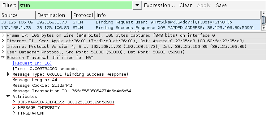
If you have ever had to answer the "What is my public IP address?"
question, then you’ve effectively performed a manual "STUN lookup."
The STUN protocol allows the browser to learn if it’s behind a NAT
and to discover its public IP and port; see STUN, TURN, and ICE.
Whenever a new candidate (an IP, port tuple) is discovered, the
agent automatically registers it with the RTCPeerConnection object and
notifies the application via a callback function
( STUN server, configured to use Google's public test server
TURN server for relaying data if peer-to-peer connection fails
Apply local session description: initiates ICE gathering
process
Subscribe to ICE events and listen for ICE gathering
completion
Regenerate the SDP offer (now with discovered ICE candidates)
Private ICE candidate (192.168.1.73:60834) for the peer
Public ICE candidate (50.76.44.100:69834) returned by the STUN
server
The previous example uses Google’s public demo STUN server.
Unfortunately, STUN alone may not be sufficient (see STUN
and TURN in Practice), and you may also need to provide a TURN
server to guarantee connectivity for peers that cannot establish a
direct peer-to-peer connection (~8% of users).
As the example illustrates, the ICE agent handles most of the
complexity on our behalf: the ICE gathering process is triggered
automatically, STUN lookups are performed in the background, and the
discovered candidates are registered with the RTCPeerConnection object.
Once the process is complete, we can generate the SDP offer and use the
signaling channel to deliver it to the other peer.
Then, once the ICE candidates are received by the other peer, we are
ready to begin the second phase of establishing a peer-to-peer
connection: once the remote session description is set on the
RTCPeerConnection object, which now contains a list of candidate IP and
port tuples for the other peer, the ICE agent begins connectivity
checks (Figure 18-8) to
see if it can reach the other party.
The ICE agent sends a message (a STUN binding request), which the
other peer must acknowledge with a successful STUN response. If this
completes, then we finally have a routing path for a peer-to-peer
connection! Conversely, if all candidates fail, then either the
RTCPeerConnection is marked as failed, or the connection falls back to
a TURN relay server to establish the connection.
The ICE agent automatically ranks and prioritizes the order in
which the candidate connection checks are performed: local IP
addresses are checked first, then public, and TURN is used as a last
resort. Once a connection is established, the ICE agent continues to
issue periodic STUN requests to the other peer. This serves as a
connection keepalive.
Phew! As we said at the beginning of this section, initiating a
peer-to-peer connection requires (much) more work than opening an XHR,
EventSource, or a new WebSocket session. The good news is, most of this
work is done on our behalf by the browser. However, for performance
reasons, it is important to keep in mind that the process may incur
multiple roundtrips between the STUN servers and between the individual
peers before we can begin transmitting data—that is, assuming ICE
negotiation is successful.
The ICE gathering process is anything but instantaneous: retrieving
local IP addresses is fast, but querying the STUN server requires a
roundtrip to the external server, followed by another round of STUN
connectivity checks between the individual peers. Trickle ICE is an
extension to the ICE protocol that allows incremental gathering and
connectivity checks between the peers. The core idea is very simple:
Both peers exchange SDP offers without ICE candidates.
ICE candidates are sent via the signaling channel as they are
discovered.
ICE connectivity checks are run as soon as the new candidate
description is available.
In short, instead of waiting for the ICE gathering process to
complete, we rely on the signaling channel to deliver incremental
updates to the other peer, which helps accelerate the process. The
WebRTC implementation is also fairly simple:
Trickle ICE generates more traffic over the signaling channel, but
it can yield a significant improvement in the time required to initiate
the peer-to-peer connection. For this reason, it is also the
recommended strategy for all WebRTC applications: send the offer as
soon as possible, and then trickle ICE candidates as they are
discovered.
The built-in ICE framework manages candidate discovery, connectivity
checks, keepalives, and more. If all works well, then all of this work
is completely transparent to the application: the only thing we have to
do is specify the STUN and TURN servers when initializing the
RTCPeerConnection object. However, not all connections will succeed,
and it is important to be able to isolate and resolve the problem. To
do so, we can query the status of the ICE agent and subscribe to its
notifications:
The The object was just created and no networking has occurred yet.
The ICE agent is in the process of gathering local candidates.
The ICE agent has completed the gathering process.
On the other hand, the The ICE agent is gathering candidates and/or waiting for remote
candidates to be supplied.
The ICE agent has received remote candidates on at least one
component and is checking candidate pairs but has not yet found a
connection. In addition to checking, it may also still be
gathering.
The ICE agent has found a usable connection for all components
but is still checking other candidate pairs to see if there is a
better connection. It may also still be gathering.
The ICE agent has finished gathering and checking and found a
connection for all components.
The ICE agent is finished checking all candidate pairs and
failed to find a connection for at least one component. Connections
may have been found for some components.
Liveness checks have failed for one or more components. This is
more aggressive than failed and may trigger intermittently (and
resolve itself without action) on a flaky network.
The ICE agent has shut down and is no longer responding to STUN
requests.
A WebRTC session may require multiple streams for delivering audio,
video, and application data. As a result, a successful connection is
one that is able to establish connectivity for all the requested
streams. Further, due to the unreliable nature of peer-to-peer
connectivity, there are no guarantees that once the connection is
established that it will stay that way: the connection may periodically
flip between connected and disconnected states while the ICE agent
attempts to find the best possible path to re-establish connectivity.
The first and primary goal for the ICE agent is to identify a
viable routing path between the peers. However, it doesn’t stop
there. Even once connected, the ICE agent may periodically try other
candidates to see if it can deliver better performance via an
alternate route.
We have covered a lot of ground: we’ve discussed signaling, the
offer-answer workflow, session parameter negotiation with SDP, and took
a deep dive into the inner workings of the ICE protocol required to
establish a peer-to-peer connection. Finally, we now have all the
necessary pieces to initiate a peer-to-peer connection over WebRTC.
We have been filling in all the necessary pieces bit by bit
throughout the preceding pages, but now let’s take a look at a
complete example for the peer responsible for initiating the WebRTC
connection:
Video element for output of local stream
Video element for output of remote stream
Initialize shared signaling channel
Initialize peer connection object
Acquire local audio and video streams
Register local MediaStream with peer connection
Output local video stream to video element (self view)
Generate SDP offer describing peer connection and send to
peer
Trickle ICE candidates to the peer via the signaling channel
Register remote ICE candidate to begin connectivity checks
Output remote video stream to video element (remote view)
The entire process can be a bit daunting on the first pass, but
now that we understand how all the pieces work, it is fairly
straightforward: initialize the peer connection and the signaling
channel, acquire and register media streams, send the offer, trickle
ICE candidates, and finally output the acquired media streams. A more
complete implementation can also register additional callbacks to
track ICE gathering and connection states and provide more feedback
to the user.
Once the connection is established, the application can still
add and remove streams from the RTCPeerConnection object. Each time
this happens, an automatic SDP renegotiation is invoked, and the
same initialization procedure is repeated.
The process to answer the request for a new WebRTC connection is
very similar, with the only major difference being that most of the
logic is executed when the signaling channel delivers the SDP offer.
Let’s take a hands-on look:
Not surprisingly, the code looks very similar. The only major
difference, aside from initiating the peer connection workflow based
on an offer message delivered via the shared signaling channel, is
that the preceding code is generating an SDP answer (via
With that, we can copy the code, add an implementation for the
signaling channel, and we have a real-time, peer-to-peer video and
audio session videoconferencing application running in the
browser—not bad for fewer than 100 lines of JavaScript code!
§Signaling and
Session Negotiation


§Session
Description Protocol (SDP)
var signalingChannel = new SignalingChannel();
var pc = new RTCPeerConnection({});

navigator.getUserMedia({ "audio": true }, gotStream, logError);

function gotStream(stream) {
  pc.addStream(stream);

  pc.createOffer(function(offer) {
    pc.setLocalDescription(offer);
    signalingChannel.send(offer.sdp);
  });
}

function logError() { ... }
createOffer() to generate the SDP description of the
intended session. What does the generated SDP contain? Let’s take a
look:
(... snip ...)
m=audio 1 RTP/SAVPF 111 ...
a=extmap:1 urn:ietf:params:rtp-hdrext:ssrc-audio-level
a=candidate:1862263974 1 udp 2113937151 192.168.1.73 60834 typ host ...
a=mid:audio
a=rtpmap:111 opus/48000/2
a=fmtp:111 minptime=10
(... snip ...)

§Interactive Connectivity Establishment (ICE)
a=candidate line lists a private
(192.168.x.x) IP address for the peer initiating the session; see
Reserved
Private Network Ranges.
onicecandidate). Once the ICE gathering is complete, the
same callback is fired to notify the application. Let’s extend our
earlier example to work with ICE:
var ice = {"iceServers": [
  {"url": "stun:stun.l.google.com:19302"},
  {"url": "turn:turnserver.com", "username": "user", "credential": "pass"}
]};

var signalingChannel = new SignalingChannel();
var pc = new RTCPeerConnection(ice);

navigator.getUserMedia({ "audio": true }, gotStream, logError);

function gotStream(stream) {
  pc.addStream(stream);

  pc.createOffer(function(offer) {
    pc.setLocalDescription(offer);
  });
}

pc.onicecandidate = function(evt) {
  if (evt.target.iceGatheringState == "complete") {
      local.createOffer(function(offer) {
        console.log("Offer with ICE candidates: " + offer.sdp);
        signalingChannel.send(offer.sdp);
      });
  }
}

...

// Offer with ICE candidates:
// a=candidate:1862263974 1 udp 2113937151 192.168.1.73 60834 typ host ...
// a=candidate:2565840242 1 udp 1845501695 50.76.44.100 60834 typ srflx ...
§Incremental
Provisioning (Trickle ICE)
var ice = {"iceServers": [
  {"url": "stun:stun.l.google.com:19302"},
  {"url": "turn:turnserver.com", "username": "user", "credential": "pass"}
]};

var pc = new RTCPeerConnection(ice);
navigator.getUserMedia({ "audio": true }, gotStream, logError);

function gotStream(stream) {
  pc.addStream(stream);

  pc.createOffer(function(offer) {
    pc.setLocalDescription(offer);
    signalingChannel.send(offer.sdp);
  });
}

pc.onicecandidate = function(evt) {
  if (evt.candidate) {
    signalingChannel.send(evt.candidate);
  }
}

signalingChannel.onmessage = function(msg) {
  if (msg.candidate) {
    pc.addIceCandidate(msg.candidate);
  }
}
§Tracking ICE Gathering and Connectivity Status
var ice = {"iceServers": [
  {"url": "stun:stun.l.google.com:19302"},
  {"url": "turn:turnserver.com", "username": "user", "credential": "pass"}
]};

var pc = new RTCPeerConnection(ice);

logStatus("ICE gathering state: "  + pc.iceGatheringState);
pc.onicecandidate = function(evt) {
   logStatus("ICE gathering state change: " + evt.target.iceGatheringState);
}

logStatus("ICE connection state: " + pc.iceConnectionState);
pc.oniceconnectionstatechange = function(evt) {
  logStatus("ICE connection state change: " + evt.target.iceConnectionState);
}
iceGatheringState attribute, as its name implies,
reports the status of the candidate gathering process for the local
peer. As a result, it can be in three different states:
new
gathering
complete
iceConnectionState attribute
reports the status of the peer-to-peer connection (Figure 18-9), which can be in one
of seven possible states:
new
checking
connected
completed
failed
disconnected
closed

§Putting It All Together
Initiating a WebRTC connection
<video id="local_video" autoplay></video>
<video id="remote_video" autoplay></video>

<script>
  var ice = {"iceServers": [
    {"url": "stun:stunserver.com:12345"},
    {"url": "turn:turnserver.com", "username": "user", "credential": "pass"}
  ]};

  var signalingChannel = new SignalingChannel();
  var pc = new RTCPeerConnection(ice);

  navigator.getUserMedia({ "audio": true, "video": true }, gotStream, logError);

  function gotStream(evt) {
    pc.addStream(evt.stream);

    var local_video = document.getElementById('local_video');
    local_video.src = window.URL.createObjectURL(evt.stream);

    pc.createOffer(function(offer) {
      pc.setLocalDescription(offer);
      signalingChannel.send(offer.sdp);
    });
  }

  pc.onicecandidate = function(evt) {
    if (evt.candidate) {
      signalingChannel.send(evt.candidate);
    }
  }

  signalingChannel.onmessage = function(msg) {
    if (msg.candidate) {
      pc.addIceCandidate(msg.candidate);
    }
  }

  pc.onaddstream = function (evt) {
    var remote_video = document.getElementById('remote_video');
    remote_video.src = window.URL.createObjectURL(evt.stream);
  }

  function logError() { ... }
</script>
Responding to a WebRTC connection
<video id="local_video" autoplay></video>
<video id="remote_video" autoplay></video>

<script>
  var signalingChannel = new SignalingChannel();

  var pc = null;
  var ice = {"iceServers": [
    {"url": "stun:stunserver.com:12345"},
    {"url": "turn:turnserver.com", "username": "user", "credential": "pass"}
  ]};

  signalingChannel.onmessage = function(msg) {
    if (msg.offer) {
      pc = new RTCPeerConnection(ice);
      pc.setRemoteDescription(msg.offer);

      pc.onicecandidate = function(evt) {
        if (evt.candidate) {
          signalingChannel.send(evt.candidate);
        }
      }

      pc.onaddstream = function (evt) {
        var remote_video = document.getElementById('remote_video');
        remote_video.src = window.URL.createObjectURL(evt.stream);
      }

      navigator.getUserMedia({ "audio": true, "video": true },
        gotStream, logError);

    } else if (msg.candidate) {
      pc.addIceCandidate(msg.candidate);
    }
  }

  function gotStream(evt) {
    pc.addStream(evt.stream);

    var local_video = document.getElementById('local_video');
    local_video.src = window.URL.createObjectURL(evt.stream);

    pc.createAnswer(function(answer) {
      pc.setLocalDescription(answer);
      signalingChannel.send(answer.sdp);
    });
  }

  function logError() { ... }
</script>
createAnswer) instead of an offer object. Otherwise, the
process is symmetric: initialize the peer connection, acquire and
register media streams, send the answer, trickle ICE candidates, and
finally output the acquired media streams.
§Delivering Media and Application Data
Establishing a peer-to-peer connection takes quite a bit of work. However, even once the clients complete the answer-offer workflow and each client performs its NAT traversals and STUN connectivity checks, we are still only halfway up our WebRTC protocol stack (Figure 18-3). At this point, both peers have raw UDP connections open to each other, which provides a no-frills datagram transport, but as we know that is not sufficient on its own; see Optimizing for UDP.
Without flow control, congestion control, error checking, and some mechanism for bandwidth and latency estimation, we can easily overwhelm the network, which would lead to degraded performance for both peers and those around them. Further, UDP transfers data in the clear, whereas WebRTC requires that we encrypt all communication! To address this, WebRTC layers several additional protocols on top of UDP to fill in the gaps:
-
Datagram Transport Layer Security (DTLS) is used to negotiate the secret keys for encrypting media data and for secure transport of application data.
-
Secure Real-Time Transport (SRTP) is used to transport audio and video streams.
-
Stream Control Transport Protocol (SCTP) is used to transport application data.
§Secure Communication with DTLS
WebRTC specification requires that all transferred data—audio, video, and custom application payloads—must be encrypted while in transit. The Transport Layer Security (Transport Layer Security (TLS)) protocol would, of course, be a perfect fit, except that it cannot be used over UDP, as it relies on reliable and in-order delivery offered by TCP. Instead, WebRTC uses DTLS, which provides equivalent security guarantees.
DTLS is deliberately designed to be as similar to TLS as possible. In fact, DTLS is TLS, but with a minimal number of modifications to make it compatible with datagram transport offered by UDP. Specifically, DTLS addresses the following problems:
-
TLS requires reliable, in-order, and fragmentation friendly delivery of handshake records to negotiate the tunnel.
-
TLS integrity checks may fail if records are fragmented across multiple packets.
-
TLS integrity checks may fail if records are processed out of order.
Refer to TLS Handshake and TLS Record Protocol for a full discussion on the handshake sequence and layout of the record protocol.
There are no simple workarounds for fixing the TLS handshake
sequence: each record serves a purpose, each must be sent in the exact
order required by the handshake algorithm, and some records may easily
span multiple packets. As a result, DTLS implements a "mini-TCP"
(Figure 18-11) just
for the handshake sequence.
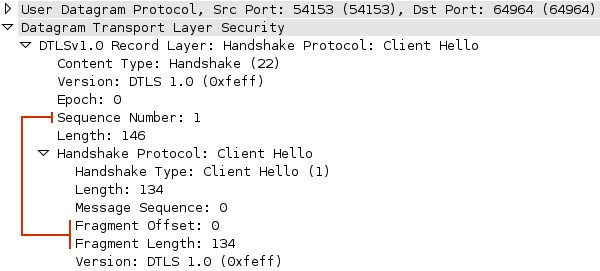
DTLS extends the base TLS record protocol by adding an explicit fragment offset and sequence number for each handshake record. This addresses the in-order delivery requirement and allows large records to be fragmented across packets and reassembled by the other peer. DTLS handshake records are transmitted in the exact order specified by the TLS protocol; any other order is an error. Finally, DTLS must also deal with packet loss: both sides use simple timers to retransmit handshake records if the reply is not received within an expected interval.
The combination of the record sequence number, offset, and
retransmission timer allows DTLS to perform the handshake
(Figure 18-12) over
UDP. To complete this sequence, both network peers generate self-signed
certificates and then follow the regular TLS handshake protocol.

The DTLS handshake requires two roundtrips to complete—an important aspect to keep in mind, as it adds extra latency to setup of the peer-to-peer connection.
The WebRTC client automatically generates self-signed certificates for each peer. As a result, there is no certificate chain to verify. DTLS provides encryption and integrity, but defers authentication to the application; see Encryption, Authentication, and Integrity. Finally, with the handshake requirements satisfied, DTLS adds two important rules to account for possible fragmentation and out-of-order processing of regular records:
-
DTLS records must fit into a single network packet.
-
A block cipher must be used for encrypting record data.
A regular TLS record can be up to 16 KB in size. TCP handles the fragmentation and reassembly, but UDP provides no such services. As a result, to preserve the out-of-order and best-effort semantics of the UDP protocol, each DTLS record carrying application data must fit into a single UDP packet. Similarly, stream ciphers are disallowed because they implicitly rely on in-order delivery of record data.
§Delivering Media with SRTP and SRTCP
WebRTC provides media acquisition and delivery as a fully managed
service: from camera to the network, and from network to the screen.
The WebRTC application specifies the media constraints to acquire the
streams and then registers them with the RTCPeerConnection object
(Figure 18-13).
From there, the rest is handled by the WebRTC media and network engines
provided by the browser: encoding optimization, dealing with packet
loss, network jitter, error recovery, flow, control, and more.

The implication of this architecture is that beyond specifying the initial constraints of the acquired media streams (e.g., 720p vs. 360p video), the application does not have any direct control over how the video is optimized or delivered to the other peer. This design choice is intentional: delivering a high-quality, real-time audio and video stream over an unreliable transport with fluctuating bandwidth and packet latency is a nontrivial problem. The browser solves it for us:
-
Regardless of the quality and size of provided media streams, the network stack implements its own flow and congestion control algorithms: every connection starts by streaming audio and video at a low bitrate (<500 Kbps) and then begins to adjust the quality of the streams to match the available bandwidth.
-
The media and network engines dynamically adjust the quality of the streams throughout the lifespan of the connection to adapt to the continuously changing network weather: bandwidth fluctuations, packet loss, and network jitter. In other words, WebRTC implements its own variant of adaptive streaming (see Adaptive Bitrate Streaming).
The WebRTC network engine cannot guarantee that an HD video stream provided by the application will be delivered at its highest quality: there may be insufficient bandwidth between the peers or high packet loss. Instead, the engine will attempt to adapt the provided stream to match the current conditions of the network.
An audio or video stream may be delivered at a lower quality than that of the original stream acquired by the application. However, the inverse is not true: WebRTC will not upgrade the quality of the stream. If the application provides a 360p video constraint, then that serves as a cap on the amount of bandwidth that will be used.
How does WebRTC optimize and adapt the quality of each media stream? Turns out WebRTC is not the first application to run up against the challenge of implementing real-time audio and video delivery over IP networks. As a result, WebRTC is reusing existing transport protocols used by VoIP phones, communication gateways, and numerous commercial and open source communication services:
- Secure Real-time Transport Protocol (SRTP)
-
Secure profile of the standardized format for delivery of real-time data, such as audio and video over IP networks.
- Secure Real-time Control Transport Protocol (SRTCP)
-
Secure profile of the control protocol for delivery of sender and receiver statistics and control information for an SRTP flow.
Real-Time Transport Protocol (RTP) is defined by RFC 3550. However, WebRTC requires that all communication must be encrypted while in transit. As a result, WebRTC uses the "secure profile" (RFC 3711) of RTP—hence the S in SRTP and SRTCP.
SRTP defines a standard packet format (Figure 18-14) for delivering audio and video
over IP networks. By itself, SRTP does not provide any mechanism or
guarantees on timeliness, reliability, or error recovery of the
transferred data. Instead, it simply wraps the digitized audio samples
and video frames with additional metadata to assist the receiver in
processing each stream.

-
Each SRTP packet carries an auto-incrementing sequence number, which enables the receiver to detect and account for out-of-order delivery of media data.
-
Each SRTP packet carries a timestamp, which represents the sampling time of the first byte of the media payload. This timestamp is used for synchronization of different media streams—e.g., audio and video tracks.
-
Each SRTP packet carries an SSRC identifier, which is a unique stream ID used to associate each packet with an individual media stream.
-
Each SRTP packet may contain other optional metadata.
-
Each SRTP packet carries an encrypted media payload and an authentication tag, which verifies the integrity of the delivered packet.
The SRTP packet provides all the essential information required by the media engine for real-time playback of the stream. However, the responsibility to control how the individual SRTP packets are delivered falls to the SRTCP protocol, which implements a separate, out-of-band feedback channel for each media stream.
SRTCP tracks the number of sent and lost bytes and packets, last received sequence number, inter-arrival jitter for each SRTP packet, and other SRTP statistics. Then, periodically, both peers exchange this data and use it to adjust the sending rate, encoding quality, and other parameters of each stream.
In short, SRTP and SRTCP run directly over UDP and work together to adapt and optimize the real-time delivery of the audio and video streams provided by the application. The WebRTC application is never exposed to the internals of SRTP or SRTCP protocols: if you are building a custom WebRTC client, then you will have to deal with these protocols directly, but otherwise, the browser implements all the necessary infrastructure on your behalf.
Curious to see SRTCP statistics for your WebRTC session? Check the latency, bitrate, and bandwidth reports in Chrome; see Inspecting WebRTC Connection Status with Google Chrome.
§Delivering application data with SCTP
In addition to transferring audio and video data, WebRTC allows peer-to-peer transfers of arbitrary application data via the DataChannel API. The SRTP protocol we covered in the previous section is specifically designed for media transfers and unfortunately is not a suitable transport for application data. As a result, DataChannel relies on the Stream Control Transmission Protocol (SCTP), which runs on top (Figure 18-3) of the established DTLS tunnel between the peers.
However, before we dive into the SCTP protocol itself, let’s first examine the WebRTC requirements for the RTCDataChannel interface and its transport protocol:
-
Transport must support multiplexing of multiple independent channels.
-
Each channel must support in-order or out-of-order delivery.
-
Each channel must support reliable or unreliable delivery.
-
Each channel may have a priority level defined by the application.
-
-
Transport must provide a message-oriented API.
-
Each application message may be fragmented and reassembled by the transport.
-
-
Transport must implement flow and congestion control mechanisms.
-
Transport must provide confidentiality and integrity of transferred data.
The good news is that the use of DTLS already satisfies the last
criteria: all application data is encrypted within the payload of the
record, and confidentiality and integrity are guaranteed. However, the
remaining requirements are a nontrivial set to satisfy! UDP provides
unreliable, out-of-order datagram delivery, but we also need TCP-like
reliable delivery, channel multiplexing, priority support, message
fragmentation, and more. That’s where SCTP comes in.
TCP
UDP
SCTP
Reliability
reliable
unreliable
configurable
Delivery
ordered
unordered
configurable
Transmission
byte-oriented
message-oriented
message-oriented
Flow control
yes
no
yes
Congestion control
yes
no
yes
SCTP is a transport protocol, similar to TCP and UDP, which can run directly on top of the IP protocol. However, in the case of WebRTC, SCTP is tunneled over a secure DTLS tunnel, which itself runs on top of UDP.
SCTP provides the best features of TCP and UDP: message-oriented API, configurable reliability and delivery semantics, and built-in flow and congestion-control mechanisms. A full analysis of the protocol is outside the scope of our discussion, but, briefly, let’s introduce some SCTP concepts and terminology:
- Association
-
A synonym for a connection.
- Stream
-
A unidirectional channel within which application messages are delivered in sequence, unless the channel is configured to use the unordered delivery service.
- Message
-
Application data submitted to the protocol.
- Chunk
-
The smallest unit of communication within an SCTP packet.
A single SCTP association between two endpoints may carry multiple independent streams, each of which communicates by transferring application messages. In turn, each message may be split into one or more chunks, which are delivered within SCTP packets (Figure 18-15) and then get reassembled at the other end.
Does this description sound familiar? It definitely should! The
terms are different, but the core concepts are identical to those of
the HTTP/2 framing layer; see Streams, Messages, and
Frames. The difference here is that SCTP implements this
functionality at a "lower layer," which enables efficient transfer and
multiplexing of arbitrary application data.

An SCTP packet consists of a common header and one or more control or data chunks. The header carries 12 bytes of data, which identify the source and destination ports, a randomly generated verification tag for the current SCTP association, and the checksum for the entire packet. Following the header, the packet carries one or more control or data chunks; the previous diagram is showing an SCTP packet with a single data chunk:
-
All data chunks have a 0×0 data type.
-
The unordered (U) bit indicates whether this is an unordered DATA chunk.
-
B and E bits are used to indicate the beginning and end of a message split across multiple chunks: B=1, E=0 indicates the first fragment of a message; B=0, E=0 indicates a middle piece; B=0, E=1 indicates the last fragment; B=1, E=1 indicates an unfragmented message.
-
Length indicates the size of the DATA chunk, which includes the header—i.e., 16 bytes for chunk header, plus size of payload data.
-
Transmission sequence number (TSN) is a 32-bit number used internally by SCTP to acknowledge receipt of the packet and detect duplicate deliveries.
-
Stream identifier indicates the stream to which the chunk belongs.
-
Stream sequence number is an auto-incremented message number for the associated stream; fragmented messages carry the same sequence number.
-
Payload protocol identifier (PPID) is a custom field filled in by the application to communicate additional metadata about the transferred chunk.
DataChannel uses the PPID field in the SCTP header to communicate the type of transferred data: 0×51 for UTF-8 and 0×52 for binary application payloads.
That’s a lot of detail to absorb in one go. Let’s review it once again, this time in the context of the earlier WebRTC and DataChannel API requirements:
-
The SCTP header contains a few redundant fields: we are tunneling SCTP over UDP, which already specifies the source and destination ports (Figure 3-2).
-
SCTP handles message fragmentation with the help of the
B,EandTSNfields in the header: each chunk indicates its position (first, middle, or last), and the TSN value is used to order the middle chunks. -
SCTP supports stream multiplexing: each stream has a unique stream identifier, which is used to associate each data chunk with one of the active streams.
-
SCTP assigns an individual sequence number to each application message, which allows it to provide in-order delivery semantics. Optionally, if the unordered bit is set, then SCTP continues to use the sequence number to handle message fragmentation, but can deliver individual messages out of order.
In total, SCTP adds 28 bytes of overhead to each data chunk: 12 bytes for the common header and 16 bytes for the data chunk header followed by the application payload.
How does an SCTP negotiate the starting parameters for the association? Each SCTP connection requires a handshake sequence similar to TCP! Similarly, SCTP also implements TCP-friendly flow and congestion control mechanisms: both protocols use the same initial congestion window size and implement similar logic to grow and reduce the congestion window once the connection enters the congestion-avoidance phase.
For a review on TCP handshake latencies, slow-start, and flow control, refer to Building Blocks of TCP. The SCTP handshake and congestion and flow-control algorithms used for WebRTC are different but serve the same purpose and have similar costs and performance implications.
We are getting close to satisfying all the WebRTC requirements, but unfortunately, even with all of that functionality, we are still short of a few required features:
-
The base SCTP standard (RFC 4960) provides a mechanism for unordered delivery of messages but no facilities for configuring the reliability of each message. To address this, WebRTC clients must also use the "Partial Reliability Extension" (RFC 3758), which extends the SCTP protocol and allows the sender to implement custom delivery guarantees, a critical feature for DataChannel.
-
SCTP does not provide any facilities for prioritizing individual streams; there are no fields within the protocol to carry the priority. As a result, this functionality has to be implemented higher in the stack.
In short, SCTP provides similar services as TCP, but because it is tunneled over UDP and is implemented by the WebRTC client, it offers a much more powerful API: in-order and out-of-order delivery, partial reliability, message-oriented API, and more. At the same time, SCTP is also subject to handshake latencies, slow-start, and flow and congestion control—all critical components to consider when thinking about performance of the DataChannel API.
§DataChannel
DataChannel enables bidirectional exchange of arbitrary application data between peers—think WebSocket, but peer-to-peer, and with customizable delivery properties of the underlying transport. Once the RTCPeerConnection is established, connected peers can open one or more channels to exchange text or binary data:
function handleChannel(chan) {
  chan.onerror = function(error) { ... }
  chan.onclose = function() { ... }

  chan.onopen = function(evt) {
    chan.send("DataChannel connection established. Hello peer!")
  }

  chan.onmessage = function(msg) {
    if(msg.data instanceof Blob) {
      processBlob(msg.data);
    } else {
      processText(msg.data);
    }
  }
}

var signalingChannel = new SignalingChannel();
var pc = new RTCPeerConnection(iceConfig);

var dc = pc.createDataChannel("namedChannel", {reliable: false});

...

handleChannel(dc);
pc.ondatachannel = handleChannel;
The DataChannel API intentionally mirrors that of WebSocket: each
established channel fires the same onerror,
onclose, onopen, and onmessage
callbacks, as well as exposes the same binaryType,
bufferedAmount, and protocol fields on the
channel.
However, because DataChannel is peer-to-peer and runs over a more flexible transport protocol, it also offers a number of additional features not available to WebSocket. The preceding code example highlights some of the most important differences:
-
Unlike the WebSocket constructor, which expects the URL of the WebSocket server, DataChannel is a factory method on the RTCPeerConnection object.
-
Unlike WebSocket, either peer can initiate a new DataChannel session: the
ondatachannelcallback is fired when a new DataChannel session is established. -
Unlike WebSocket, which runs on top of reliable and in-order TCP transport, each DataChannel can be configured with custom delivery and reliability semantics.
§Setup and Negotiation
Regardless of the type of transferred data—audio, video, or application data—the two participating peers must first complete the full offer/answer workflow, negotiate the used protocols and ports, and successfully complete their connectivity checks; see Establishing a Peer-to-Peer Connection.
In fact, as we now know, media transfers run over SRTP, whereas DataChannel uses the SCTP protocol. As a result, when the initiating peer first makes the connection offer, or when the answer is generated by the other peer, the two must specifically advertise the parameters for the SCTP association within the generated SDP strings:
(... snip ...)
m=application 1 DTLS/SCTP 5000
c=IN IP4 0.0.0.0
a=mid:data
a=fmtp:5000 protocol=webrtc-datachannel; streams=10
(... snip ...)
As previously, the RTCPeerConnection object handles all the necessary generation of the SDP parameters as long as one of the peers registers a DataChannel prior to generating the SDP description of the session. In fact, the application can establish a data-only peer-to-peer connection by setting explicit constraints to disable audio and video transfers:
var signalingChannel = new SignalingChannel();
var pc = new RTCPeerConnection(iceConfig);

var dc = pc.createDataChannel("namedChannel", {reliable: false});

var mediaConstraints = {
  mandatory: {
      OfferToReceiveAudio: false,
      OfferToReceiveVideo: false
  }
};

pc.createOffer(function(offer) { ... }, null, mediaConstraints);

...
With the SCTP parameters negotiated between the peers, we are almost
ready to begin exchanging application data. Notice that the SDP snippet
we saw earlier doesn’t mention anything about the parameters of each
DataChannel—e.g., protocol, reliability, or in-order or out-of-order
flags. As a result, before any application data can be sent, the WebRTC
client initiating the connection also sends a
DATA_CHANNEL_OPEN message (Figure 18-16) which describes the type,
reliability, used application protocol, and other parameters of the
channel.

The DATA_CHANNEL_OPEN message is similar to the
HEADERS frame in HTTP/2: it implicitly opens a new
stream, and data frames can be sent immediately after it; see
Initiating
a New Stream. For more information on the DataChannel protocol,
refer to
http://tools.ietf.org/html/draft-jesup-rtcweb-data-protocol.
Once the channel parameters are communicated, both peers can begin exchanging application data. Under the hood, each established channel is delivered as an independent SCTP stream: the channels are multiplexed over the same SCTP association, which avoids head-of-line blocking between the different streams and allows for simultaneous delivery of multiple channels over the same SCTP association.
§Configuring Message Order and Reliability
DataChannel enables peer-to-peer transfers of arbitrary application data via a WebSocket-compatible API: this by itself is a unique and a powerful feature. However, DataChannel also offers a much more flexible transport, which allows us to customize the delivery semantics of each channel to match the requirements of the application and the type of data being transferred.
-
DataChannel can provide in-order or out-of-order delivery of messages.
-
DataChannel can provide reliable or partially reliable delivery of messages.
Configuring the channel to use in-order and reliable delivery is, of course, equivalent to TCP: the same delivery guarantees as a regular WebSocket connection. However, and this is where it starts to get really interesting, DataChannel also offers two different policies for configuring partial reliability of each channel:
- Partially reliable delivery with retransmit
-
Messages will not be retransmitted more times than specified by the application.
- Partially reliable delivery with timeout
-
Messages will not be retransmitted after a specified lifetime (in milliseconds) by the application.
Both strategies are implemented by the WebRTC client, which means
that all the application has to do is decide on the appropriate
delivery model and set the right parameters on the channel. There is no
need to manage application timers or retransmission counters. Let’s
take a closer look at our configuration options:
Ordered
Reliable
Partial reliability policy
Ordered + reliable
yes
yes
n/a
Unordered + reliable
no
yes
n/a
Ordered + partially reliable (retransmit)
yes
partial
retransmission count
Unordered + partially reliable (retransmit)
no
partial
retransmission count
Ordered + partially reliable (timed)
yes
partial
timeout (ms)
Unordered + partially reliable (timed)
no
partial
timeout (ms)
Ordered and reliable delivery is self-explanatory: it’s TCP. On the other hand, unordered and reliable delivery is already much more interesting—it’s TCP, but without the head-of-line blocking problem; see Head-of-Line Blocking.
When configuring a partially reliable channel, it is important to keep in mind that the two retransmission strategies are mutually exclusive. The application can specify either a timeout or a retransmission count, but not both; doing so will raise an error. With that, let’s take a look at the JavaScript API for configuring the channel:
conf = {};
conf = { ordered: false };
conf = { ordered: true,  maxRetransmits: customNum };
conf = { ordered: false, maxRetransmits: customNum };
conf = { ordered: true,  maxRetransmitTime: customMs };
conf = { ordered: false, maxRetransmitTime: customMs };

conf = { ordered: false, maxRetransmits: 0 };

var signalingChannel = new SignalingChannel();
var pc = new RTCPeerConnection(iceConfig);

...

var dc = pc.createDataChannel("namedChannel", conf);

if (dc.reliable) {
  ...
} else {
  ...
}
-
Default to ordered and reliable delivery (TCP)
-
Reliable, unordered delivery
-
Ordered, partially reliable with custom retransmit count
-
Unordered, partially reliable with custom retransmit count
-
Ordered, partially reliable with custom retransmit timeout
-
Unordered, partially reliable with custom retransmit timeout
-
Unordered, unreliable delivery (UDP)
-
Initialize DataChannel with specified order and reliability configuration
Once a DataChannel is initialized, the application can access the
maxRetransmits and maxRetransmitTime as
read-only attributes. Also, as a convenience, the DataChannel
provides a reliable attribute, which returns false if
either of the partial-reliability strategies are used.
Each DataChannel can be configured with custom order and reliability parameters, and the peers can open multiple channels, all of which will be multiplexed over the same SCTP association. As a result, each channel is independent of the others, and the peers can use different channels for different types of data—e.g., reliable and in-order delivery for peer-to-peer chat and partially reliable and out-of-order delivery for transient or low-priority application updates.
§Partially Reliable Delivery and Message Size
The use of a partially reliable channel requires additional design consideration from the application. Specifically, the application must pay close attention to the message size: nothing is stopping the application from passing in a large message, which will be fragmented across multiple packets, but doing so will likely yield very poor results. To illustrate this in action, let’s assume the following scenario:
-
Two peers have negotiated an out-of-order, unreliable DataChannel.
-
The channel is configured with maxRetransmits set to 0, aka plain UDP.
-
-
The packet loss between the peers is ~1%.
-
One of the peers is trying to send a large, 120 KB message.
WebRTC clients set the maximum transmission unit for an SCTP packet to 1,280 bytes, which is the minimum and recommended MTU for an IPv6 packet. But we must also account for the overhead of IP, UDP, DTLS, and SCTP protocols: 20–40 bytes, 8 bytes, 20–40 bytes, and 28 bytes, respectively. Let’s round this up to ~130 bytes of overhead, which leaves us with ~1,150 bytes of payload data per packet and a total of 107 packets to deliver the 120 KB application message.
So far so good, but the packet loss probability for each individual packet is 1%. As a result, if we fire off all 107 packets over the unreliable channel, we are now looking at a very high probability of losing at least one of them en route! What will happen in this case? Even if all but one of the packets make it, the entire message will be dropped.
To address this, an application has two strategies: it can add a retransmit strategy (based on count or timeout), and it can decrease the size of the transferred message. In fact, for best results, it should do both.
-
When using an unreliable channel, ideally, each message should fit into a single packet; the message should be less than 1,150 bytes in size.
-
If a message cannot fit into a single packet, then a retransmit strategy should be used to improve the odds of delivering the message.
Packet-loss rates and latency between the peers are unpredictable and vary based on current network weather. As a result, there is no one single and optimal setting for the retransmit count or timeout values. To deliver the best results over an unreliable channel, keep the messages as small as possible.
§WebRTC Use Cases and Performance
Implementing a low-latency, peer-to-peer transport is a nontrivial engineering challenge: there are NAT traversals and connectivity checks, signaling, security, congestion control, and myriad other details to take care of. WebRTC handles all of the above and more, on our behalf, which is why it is arguably one of the most significant additions to the web platform since its inception. In fact, it’s not just the individual pieces offered by WebRTC, but the fact that all the components work together to deliver a simple and unified API for building peer-to-peer applications in the browser.
However, even with all the built-in services, designing efficient and
high-performance peer-to-peer applications still requires a great amount
of careful thought and planning: peer-to-peer does not mean high
performance on its own. If anything, the increased variability in
bandwidth and latency between the peers, and the high demands of media
transfers, as well as the peculiarities of unreliable delivery, make it
an even harder engineering challenge.
Peer-to-peer audio and video streaming are one of the central use
cases for WebRTC: An HD quality streams requires 1–2 Mbps of bandwidth; see
Audio
(OPUS) and Video (VP8) Bitrates.
The global average bandwidth as of Q1 2013 is just 3.1 Mbps; see
Table 1-2.
An HD stream requires, at a minimum, a 3.5G+ connection; see
Table 7-2.
The good news is that the average bandwidth capacity is continuing
to grow around the world: users are switching to broadband, and 3.5G+
and 4G adoption is ramping up. However, even with optimistic growth
projections, while HD streaming is now becoming viable, it is not a
guarantee! Similarly, latency is a perennial problem, especially for
real-time delivery, and doubly so for mobile clients. 4G will
definitely help, but 3G networks are not going away anytime soon
either.
To complicate matters further, the connections offered by most
ISPs and mobile carriers are not symmetric: most users have
significantly higher downlink throughput than uplink throughput. In
fact, 10-to-1 relationships are not uncommon—e.g., 10 Mbps down, 1
Mbps up.
The net result is that you should not be surprised to see a single,
peer-to-peer audio and video stream saturate a significant amount of
users’ bandwidth, especially for mobile clients. Thinking of providing
a multiparty stream? You will likely need to do some careful planning
for the amount of available bandwidth:
A mobile client may be able to download an HD-quality stream (1
Mbps+) but may need to send a lower-quality stream due to lower
uplink throughput; different parties can stream at different
bitrates.
The audio and video streams may need to share bandwidth with
other applications and data transfers—e.g., one or more DataChannel
sessions.
Bandwidth and latency are always changing regardless of the type
of connectivity—wired or wireless—or the generation of the network,
and the application must be able to adapt to these conditions.
The good news is that the WebRTC audio and video engines work
together with the underlying network transport to probe the available
bandwidth and optimize delivery of the media streams. However,
DataChannel transfers require additional application logic: the
application must monitor the amount of buffered data and be ready to
adjust as needed.
When acquiring the audio and video streams, make sure to set the
video constraints to match the use case; see Acquiring Audio
and Video with getUserMedia.
A single peer-to-peer connection with bidirectional HD media streams
can easily use up a significant fraction of users’ bandwidth. As a
result, multiparty applications should carefully consider the
architecture (Figure 18-17) of how the individual
streams are aggregated and distributed between the peers.
One-to-one connections are easy to manage and deploy: the peers talk
directly to each other and no further optimization is required.
However, extending the same strategy to an N-way call, where each peer
is responsible for connecting to every other party (a mesh network)
would result in While mesh networks are easy to set up, they are often inefficient
for multiparty systems. To address this, an alternative strategy is to
use a "star" topology instead, where the individual peers connect to a
"supernode," which is then responsible for distributing the streams to
all connected parties. This way only one peer has to pay the cost of
handling and distributing A supernode can be another peer, or it can be a dedicated service
specifically optimized for processing and distributing real-time data;
which strategy is more appropriate depends on the context and the
application. In the simplest case, the initiator can act as a
supernode—simple, and it might just work. A better strategy might be to
pick the peer with the best available throughput, but that also
requires additional "election" and signaling mechanisms.
The criteria and the process for picking the supernode is left up
to the application, which by itself can be a big engineering
challenge. WebRTC does not provide any infrastructure to assist in
this process.
Finally, the supernode could be a dedicated and even a third-party
service. WebRTC enables peer-to-peer communication, but this does not
mean that there is no room for centralized infrastructure! Individual
peers can establish peer connections with a proxy server and still get
the benefit of both the WebRTC transport infrastructure and the
additional services offered by the server.
In addition to planning and anticipating the bandwidth requirements
of individual peer connections, every WebRTC application will require
some centralized infrastructure for signaling, NAT and firewall
traversal, identity verification, and other additional services offered
by the application.
WebRTC defers all signaling to the application, which means that the
application must at a minimum provide the ability to send and receive
messages to the other peer. The volume of signaling data sent will vary
by the number of users, the protocol, encoding of the data, and
frequency of updates. Similarly the latency of the signaling service
will have a great impact on the "call setup" time and other signaling
exchanges.
Use a low-latency transport, such as WebSocket or SSE with XHR.
Estimate and provision sufficient capacity to handle the
necessary signaling rate for all users of your application.
Optionally, once the peer connection is established, the peers
can switch to DataChannel for signaling. This can help offload the
amount of signaling traffic that must be handled by the central
server and also reduce latency for signaling communication.
Due to the prevalence of NATs and firewalls, most WebRTC
applications will require a STUN server to perform the necessary IP
lookups to establish the peer-to-peer connection. The good news is that
the STUN server is used only for connection setup, but nonetheless, it
must speak the STUN protocol and be provisioned to handle the necessary
query load.
Unless the WebRTC application is specifically designed to be
used within the same internal network, always provide a STUN server
when initiating the RTCPeerConnection object; otherwise, most
connections will simply fail.
Unlike the signaling server, which can use any protocol, the
STUN server must respond to, well, STUN requests. You will need a
public server or will have to provision your own; stund is
a popular open source implementation.
Even with STUN in place, 8%–10% of peer-to-peer connections will
likely fail due to the peculiarities of their network policies. For
example, a network administrator could block UDP outright for all the
users on the network; see STUN and TURN in
Practice. As a result, to deliver a reliable experience, the
application may also need a TURN server to relay the data between the
peers.
Relaying peer connections is suboptimal: there is an extra
network hop, and with each stream streaming at 1+ Mbps, it is easy
to saturate the capacity of any service. As a result, TURN is
always used as a last resort and requires careful capacity planning
by the application.
Multiparty services may require centralized infrastructure to help
optimize the delivery of many streams and provide additional services
as part of the RTC experience. In some ways, multiparty gateways serve
the same role as TURN but in this case for different reasons. Having
said that, unlike TURN servers, which act as simple packet proxies, a
"smart proxy" may require significantly more CPU and GPU resources to
process each individual stream prior to forwarding the final output to
each connected party.
WebRTC audio and video engines will dynamically adjust the bitrate
of the media streams to match the conditions of the network link
between the peers. The application can set and update the media
constraints (e.g., video resolution, framerate, and so on), and the
engines do the rest—this part is easy.
Unfortunately, the same can’t be said for DataChannel, which is
designed to transport arbitrary application data. Similar to WebSocket,
the DataChannel API will accept binary and UTF-8–encoded application
data, but it does not apply any further processing to reduce the size
of transferred data: it is the responsibility of the WebRTC application
to optimize the binary payloads and compress the UTF-8 content.
Further, unlike WebSocket, which runs on top of a reliable and
in-order transport, WebRTC applications must account for both the extra
overhead incurred by the UDP, DTLS, and SCTP protocols and the
peculiarities of data delivery over a partially reliable transport; see
Partially Reliable
Delivery and Message Size.
WebSocket offers a protocol extension that provides automatic
compression of transferred data. Alas, there is no equivalent for
WebRTC; all messages are transferred as they are provided by the
application.
§Audio, Video, and
Data Streaming
getUserMedia API enables the application
to acquire the media streams, and the built-in audio and video engines
handle the optimization, error recovery, and synchronization between
streams. However, it is important to keep in mind that even with
aggressive optimization and compression, audio and video delivery are
still likely to be constrained by latency and bandwidth:
§Multiparty Architectures

 connections for each peer, and a total of
  connections! If bandwidth is at a premium, as it often is
due to the much lower uplink speeds, then this type of architecture
will quickly saturate most users’ links with just a few participants.
streams, and everyone else talks directly to the supernode.
connections! If bandwidth is at a premium, as it often is
due to the much lower uplink speeds, then this type of architecture
will quickly saturate most users’ links with just a few participants.
streams, and everyone else talks directly to the supernode.
§Infrastructure and Capacity Planning
§Data Efficiency
and Compression
§Performance Checklist
Peer-to-peer architectures pose their own unique set of performance challenges for the application. Direct, one-to-one communication is relatively straightforward, but things get much more complex when more than two parties are involved, at least as far as performance is concerned. A short list of criteria to put on the agenda:
- Signaling service
-
-
Use a low-latency transport.
-
Provision sufficient capacity.
-
Consider using signaling over DataChannel once connection is established.
-
- Firewall and NAT traversal
-
-
Provide a STUN server when initiating RTCPeerConnection.
-
Use trickle ICE whenever possible—more signaling, but faster setup.
-
Provide a TURN server for relaying failed peer-to-peer connections.
-
Anticipate and provision sufficient capacity for TURN relays.
-
- Data distribution
-
-
Consider using a supernode or a dedicated intermediary for large multiparty communication.
-
Consider optimizing the received data on the intermediary prior to forwarding it to the other peers.
-
- Data efficiency
-
-
Specify appropriate media constraints for voice and video streams.
-
Optimize binary payloads sent over DataChannel.
-
Consider compressing UTF-8 content sent over DataChannel.
-
Monitor the amount of buffered data on the DataChannel and adapt to changes in the conditions of the network link.
-
- Delivery and reliability
-
-
Use out-of-order delivery to avoid head-of-line blocking.
-
If in-order delivery is used, minimize the message size to reduce the impact of head-of-line blocking.
-
Send small messages (< 1,150 bytes) to minimize the impact of packet loss on fragmented application messages.
-
Set appropriate retransmission count and timeouts for partially reliable delivery. The "right" settings depend on message size, type of application data, and latency between the peers.
-